Site pages
Current course
Participants
General
22 February - 28 February
1 March - 7 March
8 March - 14 March
15 March - 21 March
22 March - 28 March
29 March - 4 April
5 April - 11 April
12 April - 18 April
19 April - 25 April
26 April - 2 May
Lesson-16. Forces acting upon tillage tool/ implement and symbols used in tillage force analysis
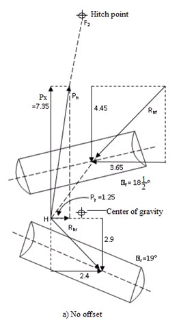
Fig. 16 (a) Thrust Force T, plus a Radial Force U
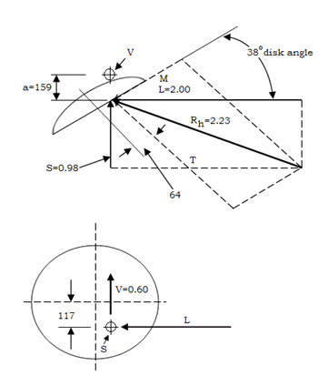 Fig. 16 (b) Horizontal Force Rh, plus Vertical Force V
L & S Components are combined into horizontal resultant Rh so that entire effect is represented by two non-intersecting forces V & Rh
Soil forces acting on a disc blade as a result of operation of cutting, pulverizing, elevating and inverting of furrow slice plus any parasitic forces acting on the disc.
(Useful forces (Tool must overcome in cutting, braking & moving of soil).
Parasitic forces (act upon stabilizing surface of disc, sole of plow, landside. It includes friction or rolling resistance.
- Resultant effect is expressed by two non-intersecting forces,
a) Thrust force T, parallel to disc axis
b) Radial force is
Thrust force always below disk centerline as soil acts against lower part of disc face.
Radial force causes rotation of disk and provides torque necessary to overcome bearing friction. It includes vertical support force on disk blade which must pass slightly to rear of disk centerline.
The resultant effect can be expressed by method which is based on longitudinal, lateral and vertical components.
As these two forces do not intersect, they introduce a couple Va that tends to rotate the implement about axis of forward travel.
This couple is always clockwise for right-hand disc plow if viewed from rear. It is opposite to effect on a mould board plow without a coulter.
Forces Acting on Disc Harrow
The forces acting upon a complete disc harrow are:
(1) Resultant soil reaction on each gang
(2) Force of gravity upon the implement and any extra mass added.
(3) Any supporting soil forces provided by wheels or as a result of being mounted on a tractor
(4) Pull of the power source.
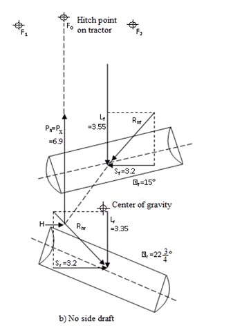
For uniform motion these forces must be in equilibrium. If there is no side draft, sum of the side component of all soil reactions must be zero. The forces indicated in figs. 18 (a), (b) and (c) can be obtained by proper application of method of statics.
Fo - hitch pt. on tractor
Qf, Qr - Disc angle
Horizontal forces:
Fig. 18 (a) shows horizontal forces acting upon offset disc harrow without wheels and operating with no side draft. Location of horizontal centre of resistance H is determined by intersection of Rhf and Rhr.
For no side draft condition hitch linkages are adjusted that hitch point Fo is directly in front of H.
- If hitch point is changed to move the implement to either right or left side draft will introduce and operating condition of harrow are changed.
If hitch linkage is changed to move the implement either to right or left side draft will introduced and operating condition of harrow are changed. Like if, hitch point moved from F0 to F2, force of equilibrium, momentarily destroyed and side components of new pull acting at H rotate the implement counter-clockwise about F2. Rotation continues until disk angle of two gangs readjusted themselves. So that difference between their lateral force components Sf and Sr becomes equal to side draft Py. Magnitude of Lf (i.e. longitudinal or directional component) and Lr and Position H also change during their re-adjustment.
No offset condition:
- Changing from condition (b) to (a) fig.18 (b) amount of soil moved by rear gang decreased.
Extreme right offset positon:
Fig 18 (c) i.e. In extreme right offset position rear gang does most of the work. Also with no side draft (Fig. 18 (a)) rear gang operates at a greater angle and moves more soil than front gang.
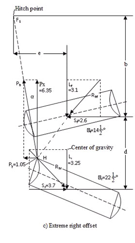 Amount of offset obtainable
Let e = amount of offset from hitch point to centre of cut.
α = horizontal angle of pull
d = Longitudinal distance between centres of two gangs.
b = longitudinal distance from centre of front gang to hitch point.
Taking moment about F1 and assume Rht and Rhr pass through centre of gangs.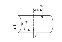
eLf + eLr + bSf – (b+d)Sr= 0
b(Sr-Sf) + dSr dSr
or, e = ______________ = btanα + _______
Lf +Lr Lf +Lr
For condition of no side draft
Sf = Sr = S & α = 0
Therefore, offset with no side draft
dS
e0 = ____ ____
Lf + Lr
Last modified: Friday, 21 March 2014, 7:21 AM