Site pages
Current course
Participants
General
Module 1. Classification of Farm Power Sources
Module 2. Classification of IC Engines & Therm...
Module 3. Performance Characteristics
Module 4. Engine Components
Module 5. Engine Operating System
Module 6.:Engine Fuel System
Module 7. Engine Governor
Module 8. Engine Cooling & Lubrication system
Module 9. Engine Ignition System
26 April - 2 May
LESSON 9. Components : Function & Material of Construction
9.1 Carburetor: Venturi flow device that meters the proper amount of fuel into the air flow by means of pressure differential. For many decades it was the basic fuel metering system on all automobile (and other) engines. It is still used on low cost small engines having jets and float as the critical sub-components of a carburetor.
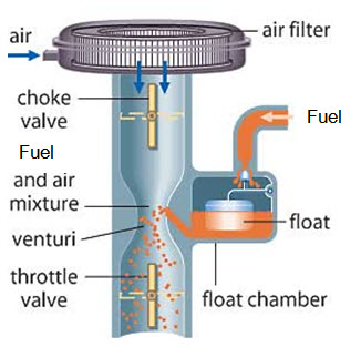
9.2 Choke: Butterfly valve at carburetor intake, used to create rich fuel-air mixture in intake system by choking/restricting the air intake for cold weather starting.
9.3 Combustion chamber: The end of the cylinder between the head and the piston face where the combustion occurs. The size of the combustion chamber continuously changes from a minimum volume when the piston is at TDC to a maximum when the piston is at BDC.
9.4 Cooling fins: The extended surfaces in the form of metal fins used air cooled engine on the outside surfaces of cylinders and head for cooling purposes by conduction and convection are known as cooling fins.
9.5 Crankcase: Part of the engine block surrounding the rotating crankshaft> in many engines the oil pan makes up part of the crankcase housing. In some high performance engines the crankcase is designed with windows between the piston bays to allow free airflow between bays. This is to reduce air pressure build up on the backside of the pistons during power and intake strokes.
9.6 Exhaust system: The flow systems for removing exhaust gases from the cylinders, treating them and exhausting them to the surroundings. It consists of an exhaust manifold (piping systems usually made of cast iron that carries exhaust gases away from the engine cylinders) that carries the exhaust gases away from the engine, a thermal or catalytic converter to reduce emissions, a muffler to reduce engine noise and a tail pipe to carry the exhaust gases away from the passenger compartment.
9.7 Fan: Most engines have fan to increase air flow through the radiator and through the engine compartment which increases the heat removal from the engine for cooling purposes. Fans can be driven mechanically (with belt) or electrically, and can run continuously or be used only when needed.
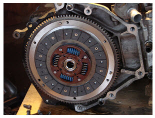
9.8 Flywheel : It is the rotating mass with large moment of inertia connected to the crankshaft of the engine. The purpose of the flywheel is to store energy and furnish a large angular momentum that that keeps the engine rotating between power strokes and smoothes out engine operation. In multiple cylinder engines, the size of flywheel is relatively smaller than the single cylinder engines. On some aircraft engines the propeller serves as the flywheel.
9.9 Fuel Injector : A pressurized nozzle that sprays fuel into the incoming air in SI engines or into the cylinder in CI engines are known as fuel injectors. In SI engines, fuel injectors are located at the intake valve ports on multipoint port injection systems.
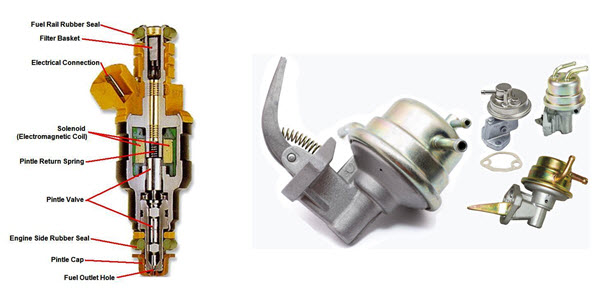
9.10 Fuel pump: Electrically or mechanically driven pump to supply fuel from the fuel tank (reservoir) to the engine is known as fuel pump. Many modern automobiles have an electrical fuel pump mounted submerged in the fuel tank. Fuel pumps are generally of two types ; inline pump (reciprocating type) for each cylinder or rotary pump (rotor type) common for all cylinders.
9.11 Glow plug: Small electrical heater resistance mounted inside the combustion chamber of many CI engines, used to preheat the chamber so that combustion will occur when first starting a cold engine. The glow plug is turned off after the engine is started.
9.12 Intake Manifold: Piping system that delivers incoming air to the cylinders usually made of cast metal, plastic, or composite material. In most SI engines, fuel is added to the air in the intake manifold system either by fuel injectors or with a carburetor. Some intake manifolds are heated to enhance fuel evaporation. The individual pipe to a single cylinder is called a runner.
9.13 Main bearing: The bearings connected to the engine block in which the crankshaft rotates are called main bearings.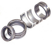
9.14 Oil pan: Oil reservoir usually bolted to the bottom of the engine block, making up part of the crankcase. It acts as the oil sump for most engines.
9.15 Oil pump: Pump used in force feed lubricating system to distribute oil from the oil sump to required lubrication points is called oil pump. The oil pump can be electrically driven but in most cases it is mechanically driven by the engine. Some small engines do not have an oil pump and are lubricated by splash distribution.
9.16 Oil sump: It is the reservoir for the oil system of the engine, commonly part of the crankcase. Some automobile engines with overhead crankshafts have a secondary oil sump in the engine head to supply lubrication to the cam and valve mechanism. Some engines have a separate closed reservoir called a dry sump.
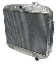
9.17 Radiator : Liquid to air heat exchanger of honey comb construction used to remove heat from the engine coolant is called radiator. The radiator usually mounted in front of the engine in the flow of air as the automobile moves forward. An engine drive or electric fan is often used to increase air flow through the radiator.
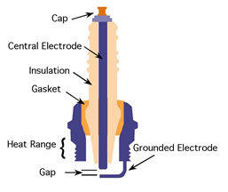
9.18 Spark plug: Electrical device used to initiate combustion in an SI engine by creating a high voltage discharge spark across an electrode gap. Spark plug is usually made of metal surrounded with ceramic insulation. Some modern spark plug has built-in pressure sensors that supply one of the inputs into engine control.
9.19 Water jacket : System of liquid flow passages surrounding the cylinders usually constructed as part of engine block and head. Engine coolant flows through the water jacket ands keeps the cylinder walls from over heating. The coolant is usually a water ethylene glycol mixture.
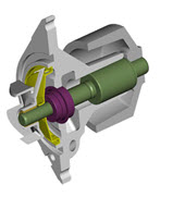
9.20 Water pump : Pump used to circulate engine coolant through the engine and radiator. It is usually mechanically run off the engine.
Last modified: Tuesday, 28 January 2014, 9:31 AM