Site pages
Current course
Participants
General
Module 1. Classification of Farm Power Sources
Module 2. Classification of IC Engines & Therm...
Module 3. Performance Characteristics
Module 4. Engine Components
Module 5. Engine Operating System
Module 6.:Engine Fuel System
Module 7. Engine Governor
Module 8. Engine Cooling & Lubrication system
Module 9. Engine Ignition System
26 April - 2 May
LESSON 10. Crank Mechanism
Crank mechanism is used to convert reciprocating motion to rotary motion and vice versa. It consists of following components.
i) Crankcase
ii) Crankshaft
iii) Main bearings
iv) Flywheel
v) Vibration dumper
vi) Crankcase breather
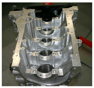
10.1 Crankcase: It is the part of the engine block which contains the rotating crankshaft and acts as engine oil reservoir as the oil pan is an integral part of the crankcase housing. Crankcase is also provided with engine breather known as crankcase breather to reduce air pressure build up on the backside of the pistons during power and intake strokes. This is also known as crankcase ventilation.

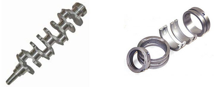
10.2 Crankshaft : Crankshaft is the engine component from where the reciprocating of the piston is taken out as work output in the form of rotary motion. The reciprocating motion of piston is transferred through the connecting rod. Crankshafts are provided with holes to provide lubrication to the moving components. Crankshafts are generally manufactured as one piece of forged heat treated alloy steel and are machined with a very high precision.
10.3 Main bearings : Main journals form the axis of the crankshaft and are supported in main bearings. These bearings are of split type and are replaceable. Bearings are made of very thin alloy lining applied on copper or steel backed surface to attain greater durability and heat dissipation.

10.4 Flywheel : The rear end of the crankshaft carries flywheel. It is the rotating mass connected to the crankshaft having large moment of inertia. The flywheel is provided to store energy and momentum that that keeps the engine rotating between power strokes and other engine strokes. In multiple cylinder engines, the size of flywheel is relatively c than the single cylinder engines.
10.5 Vibration dumpers : When engine runs continuously, due to rotational motion of the crankshaft and big end of the connecting rod, they are subjected to bend. To counter this side effect, counter weights are provided to run the engine smoothly. These are either made integral part of the crankshaft or attached separately to it. Counter weights known as vibration dumpers must be balanced carefully to eliminate undue vibration resulting from the weight of the offset cranks.
10.6 Crankcase breather : The crankcase breather is used to avoid build-up pressure in the sump and maintain normal pressure inside it. Any gas passing into the crankcase is expelled through the breather. The breather cap and the element should be cleaned periodically. The air full of dust could also get into engine through this breather cap and hence it should be maintained properly.