Site pages
Current course
Participants
General
Module 1
Module 2.
Module 3.
Module 4
22 March - 28 March
29 March - 4 April
5 April - 11 April
12 April - 18 April
19 April - 25 April
26 April - 2 May
LESSON 7. Steering Geometry, Wheel Track Adjustment
Most of the general purpose tractors are provided with adjustable type front axles. The adjustable type front axle is provided to use with modern equipments like sowing, Planting, Crop protection and harvesting operation. It is a heavy duty assembly with larger diameter kingpin & bearings.
The front axles are provided with seals to make it water proof for wet land cultivation. It has already been established that the driver can run the tractor in any direction he desires by controlling steering wheel of the steering system provided in the tractor. However, if the driver has to continually manipulate the steering wheel while doing field job or transporting on a straight road, he has to exert considerable force to turn the tractor on curves, he would be under quite a physical strain.
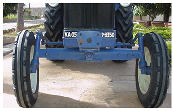
Fig: 1. View of toe-in of front axle of a tractor (Courtesy: Escort Tractor)
Front wheel alignment adjustments have been provided to eliminate these troubles and also to prevent early wear of the tyres. The front wheels have been installed on the front axle at a certain angle in accordance with the front wheel alignment.
It is only when the various elements making up this angular relation are all correct that the steering wheel becomes stable, steering becomes less tiring, and tyre wear becomes less. Even if one of these elements should be missing, the steering wheel will remain unstable.
The various elements of front wheel alignment mutually overcome each other's deficiencies and perform the following important functions:
-
Minimize steering wheel turning effort
-
Stabilize the steering wheel.
-
Provide self centring to the steering wheel,
-
Prolong the life of tyres.
Front Wheel Alignment:
The following are the factors of front wheel alignment:
a) Camber
b) Caster
c) King pin inclination
d) Toe-in
e) In tractor a, b & c items are fixed and cannot be altered, except Toe-in, which is adjustable.
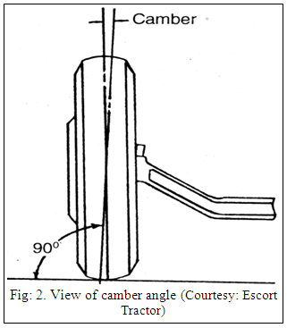
a) Camber:
The front wheels that do the steering are installed tilted outward at top. This amount of tilt is called camber. (Fig: 2.).
The front wheels tend to tilt outward at the bottom due to weight of the vehicles. Therefore, the wheels tend to pull out and to prevent this, camber is provided. Moreover, when camber is provided vehicle weight is impressed at the spindle root so that it contributes, together with the king pin inclination, toward reducing steering effort.
The camber angle is normally from 1 to 3 degrees. (Fig: 2.)
b) Caster:
The king pin is installed with its upper part slightly tilted backward. This angle of tilt is called caster.
The centre line of the tyre lies behind the point where the centre line of the king pin passes through the road surface. Because of this, the tyre rolling resistance causes the front wheel to always trail behind, resulting in the front wheel to automatically follow the direction of vehicle progress.
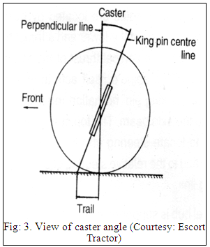
It is for this reason that when the steering wheel is turned, it returns automatically to straight ahead position when the hand is released. This is called caster effect. The caster is usually from 1 to 3 degrees.
Caster produces the recovery force to return the front wheels to straight-ahead position. This also has a reverse effect of increasing the effort required to steer. To offset this there are vehicles made with zero caster. (Fig: 3.)
c) King pin inclination:
The upper part of the king pin (or line through upper and lower ball joint) is titled inward. This tilt is called king pin inclination, and is normally around 7 degrees. The front wheels swing around the kingpins when the steering wheel is turned. If king pin is not provided, the road resistance will cause the steering wheel to become unstable. By providing king pin inclination, together with camber the distance "e" (offset), between the wheel ground-contacting centre line and the point where the king pin centre line passes through the road surface will be made very small.
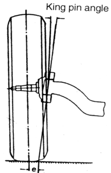
Fig: 4. View of king pin inclination (Courtesy: Escort Tractor)
This makes the steering more stable. It also reduces the force required to rotate the front wheels around the king pins, making it easier to turn the steering wheel, particularly when the vehicle is stationary.
When the steering wheel is turned, the presence of king pin inclination causes the front wheels to raise up the axle. For this reason, the vehicle weight presses down on the axle tends to return the wheels to straight-ahead position, restoring force is created. (Fig: 4.)
d) Toe-in:
The front wheels are not parallel to each other but have been made with the distance between the front parts slightly less than the distance between the rear parts. This state is called toe in. (Fig: 5.)
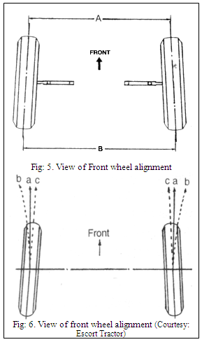
As already related, the front wheels are provided with camber so that they tend to roll outward along the dotted lines "b". Assuming that the camber is the same at both sides, the wheels will no doubt roll together with the straight ahead vehicle travel, but the tyres will slip on the road surface while doing so. This will hasten tyre wear as well as making steering unstable. The toe in has been provided to prevent these troubles. Toe in =B–A.
By providing toe in, the wheels will tend to roll inward along the dotted lines "c". This serves to counteract the force of camber tending to roll the wheels outward (along dotted lines "b") and allows the wheels to roll straight ahead without slipping. (Fig: 6.)
The toe-in is designed as the difference of the distance between the front wheel tyre centre lines at the front end and that the rear end, and is usually from 6 to 10mm (0.24-0.39 in).
The above wheel alignments have all been constructed to allow measurements or adjustments to be made by use of alignment gauges.
2. Adjustable front axle
a) Introduction
The front axle consists of a centre axle assembly, mounted centrally to the engine front support by means of a front axle support pin. This pin allows a certain amount of articulation about the centre point.
The axle sections are attached to the centre axle by means of two bolts, nuts on each side. The holes used are positioned in such a way that the track of the axle can be varied in 4 in. (1220 mm) steps from 48 in. (1220 mm) to 76 in (1930 mm)
The outer end of the axle sections accepts the front wheel spindles. These spindles are located by bushings on the axle section and at the lower end a thrust bearing is used to support the vertical thrust of the spindle of the axle section. The spindle itself acts as the "king pin" and hence the king pin inclination remains constant in relation to the axle beam. The top of each spindle has a key-way to locate steering arm, which is connected at the other end to the relative steering gear arm, by means of a drag link.
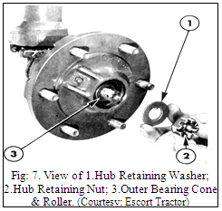
2.2 Wheel hub:
The wheel hub is supported on the wheel spindle by two opposed taper roller bearings. A nut on the spindle is used to retain the outer cone and roller assembly. This nut provides adjustments for the bearing pre-load. (Fig: 7.)
2.3 Overhauling
-
With the tractor on firm and level ground applies the handbrake and blocks the rear wheels. Slacken the front wheel retaining by 1/4 turn.
-
Use a suitable jack or hoist to support the tractor with the front wheels clear of the ground.
-
Remove the wheel retaining nuts and remove the wheel and tyre assembly.
-
Unscrew the front hub grease-retaining cap. (Fig: 7.)
-
Remove the cotter pin locating the castellated nut.
-
Remove the castellated nut and washer.
-
Remove the front wheel hub assembly and the outer cone and roller assembly from the front wheel spindle.
-
Remove the inner cone and roller assembly from the wheel spindle. Remove the grease retainer.
-
Remove the bolt and nut retaining the spindle arm. Disconnect the drag link and/or track rod.
-
Remove the spindle arm from the spindle, if the spindle arm is tight, use Puller, EF 0800, Pulling Attachment, Tool No. EF 0501 and Shaft Protector.
-
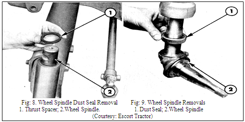
Extract the key from the spindle and remove the dust seal.(Fig: 9. & Fig: 10.)
-
Extract the heel spindle and thrust bearing from the axle section.
2.4 Re-Assembly:
-
Pack the wheel spindle thrust bearing with recommended grease and install on the wheel spindle.
-
Install the wheel spindle into the axle section housing and ensure the spindle rotates freely in the bushes.
-
Install a new wheel spindle dust seal with the groove in the periphery of the seal nearest the base.
-
Install the key in the wheel spindle. Install the spindle arm on the wheel spindle locate the key. Ensure the spindle arm bolt hole is in line with the recess in the wheel spindle. Install the spindle bolt; lock washer and nut then tighten to the correct torque. Re-connect the drag link and tighten the retaining nuts to the correct torque.
-
Install the wheel hub grease retainer on the wheel spindle.
-
Install the front wheel inner bearing cone and roller assembly on the front wheel spindle.
-
Pack the wheel hub and bearings with recommended grease. Install the wheel hub on the wheel spindle.
-
Install the front wheel outer bearing cone and roller assembly on the front wheel spindle.
-
Install the hub-retaining washer on the wheel spindle, locating the tab with the keyway in the spindle.
-
Install the wheel hub-retaining nut.
-
Tighten the bearing-retaining nut to a torque of 2.8-4.2 Kg.m.
-
Rotate the hub clockwise 3-6 revolutions.
-
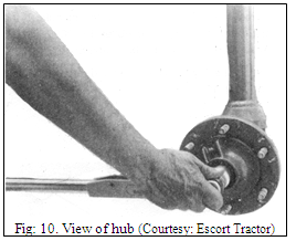
Further tighten the retaining nut to a torque of 6-8 Kg-m. (Fig: 10.)
-
Loosen the retaining nut by two flats.
-
Tighten the nut, if necessary, to the nearest position to allow insertion of a new retaining cotter pin.
-
Install the wheel and tyre assembly on the hub and 1 retain with the nuts. Tighten the nuts to the correct torque.
-
Remove the jack or hoist and the rear wheel chocks.
2.5 Adjustments:
1. Front Wheel Track Adjustment:
The front axle consists of an inverted 'U' section centre axle assembly mounted centrally to the engine front support. The method of mounting consists of two support pin is attached to the mid-point of the centre axle assembly and the rear support pin is attached to the rear extension of the centre axle, the rear axle support pin locates in a bushing in the front axle support. The front axle support pin bushing is incorporated into a bracket attached to the front axle support.
The method of mounting limits the axle assembly to a radial movement about the support pin axis. This obviates the necessity of radius rods to locate the axle. The radial movement of the axle assembly is limited by the front axle support. (Fig: 11.)
Table: 1. Track setting in tractor
|
Track Setting |
Axle Bolt |
|
|
Mm |
Locations |
|
|
1220 |
A |
C |
|
1320 |
B |
D |
|
1420 |
C |
E |
|
1520 |
D |
F |
|
1630 |
E |
G |
|
1730 |
F |
H |
|
1830 |
E |
G |
|
1930 |
F |
H |
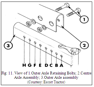
Outer axle section, consisting of an inverted ‘U’ section with a tube to accept the wheel spindle welded to the outer end, is installed into the open ends of the centre axle assembly. The centre axle assembly and the axle sections are machined to provide a series of holes that will allow the track of the axle to varied in 102 mm steps between 1320 mm and 2030 mm. (Table: 1.)
The outer end of the axle section accepts the front wheel spindle. The spindle is located in the axle section by bushings and at the lower end a thrust bearing is used to support the vertical thrust of the spindle on the axle section. The spindle acts as the kingpin and hence the king pin inclination remains constant in relation to the axle assembly. The top of each wheel spindle is keyed to locate a spindle arm.
Note: The track of the front wheels is adjustable from 1220 to 1930 mm in approximately 102 mm increments (Table: 1.). To obtain a front wheel track setting of 2030 mm it is necessary to reverse the disc of the front wheels at an axle setting of 1830 mm. It is not recommended that the wheels be reversed in the 1930 mm axle setting to give a resultant 2130 mm track as undue strain can be placed on components under high load and shock conditions.
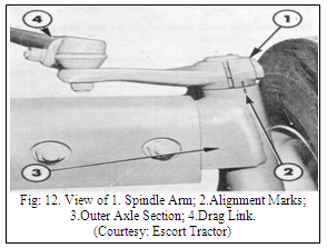
2. Toe-in Adjustment: Follow following procedure toe –in adjustments
-
On flat level ground slowly drive the tractor in a straight-ahead position. Align the alignment mark with Spindle Arm.
-
Mark the each front wheel one foot above the ground.
-
Measure and note distance between the two marks on the front wheels.
-
Maintain the straight ahead position and move the tractor forward, so that the wheels rotate through 180º and the marks on the wheel face the rear at one feet height above the ground.
-
Align the marks, measure, and note the distance between the two marks.
Note: If the measurement between the marks is more than the rear, it is toe-out and if the measurement between the marks is more than front, it is toe-in. Maintain toe-in between 0- 13mm. (Fig: 12.)
3. Wheel weights:
In order to obtain sufficient traction for maximum performance in heavy draft operations and to counter balance heavy implements, cast iron wheel weights are provided for the front (if required) and rear wheels. Four holes are provided in the front wheel disc to enable front wheel weights to be attached to the wheel. These weights are to be mounted on the inside concave surface of the disc, using two bolts to retain each weight. Each weight is 20 Kgs. and a quantity of two weights is fitted to each wheel. Thus a total combined weight of 80 Kgs. can be mounted on the front wheels.
4. Front Axle Specifications:
|
DETAILS |
FRONT AXLE |
||
|
ADJUSTABLE |
FIXED |
||
| 1. Wheel track adjustment in 100.06 mm steps |
1220-1930 mm |
- |
|
| 2. Front Axle Geometry |
|
||
|
Axle Articulation |
18º |
|
|
|
Camber Angle |
2º |
5º |
|
|
Castor Angle |
5º |
3º 30’ |
|
|
Kingpin Inclination |
9º |
6º 30’ |
|
|
Toe-in |
0-13 mm |
6-10 mm |
|
| 3. Shims for End-float on Front Axle Thickness available |
0.05mm 0.13mm 0.38mm |
|
|
| 4. Tyre Pressure Front wheel Size – 6.00X16-8 PR |
Field Work 1.8 kg/cm² Road Work 2.29 kg/cm² |
||
| 5. Recommended Grease Classification |
NL GI-2 or 3 |
|
|
5. Torque Specifications:
|
Particulars |
Kgf-m |
|
Spindle Arm Clamping Bolt |
6.21-6.90 |
|
Axle Section Bolt |
18-22 |
|
Support Pin Bolt |
19-22 |
|
Front Axle Support to Engine |
25-30 |
|
Drag Link Ball Pin Joint |
8-10 |
|
Drag Link Adjusting Clamp Bolts |
1-1.5 |
|
Front Axle Trunnions Bracket |
7.5-10 |
References:
Sharma D N. & S. Mukesh (2004). Design of Agricultural Tractor (Principles and Problems) Book Pub. Jain Brothers, New Delhi
Wadhwa D.S., Dhingra H. S. & Santokh, Singh Field operation and maintenance of tractor and farm machinery (FMP-301), laboratory manual by, Department of Farm Machinery and Power Engineering, PAU Ludhiana
Service and Maintenance Manual of Tractor by Escort Ltd. Faridabad
Sharma D. N., Tractor Manual, Department of Farm Power and Machinery, CCSHAU
Last modified: Tuesday, 11 February 2014, 7:59 AM