Site pages
Current course
Participants
General
Module 1. Hydraulic Basics
Module 2. Hydraulic Systems
MODULE 3.
MODULE 4.
MODULE 5.
MODULE 6.
MODULE 7.
MODULE 8.
19 April - 25 April
26 April - 2 May
Lesson 30 Tractor hydraulics and nudging system
Introduction
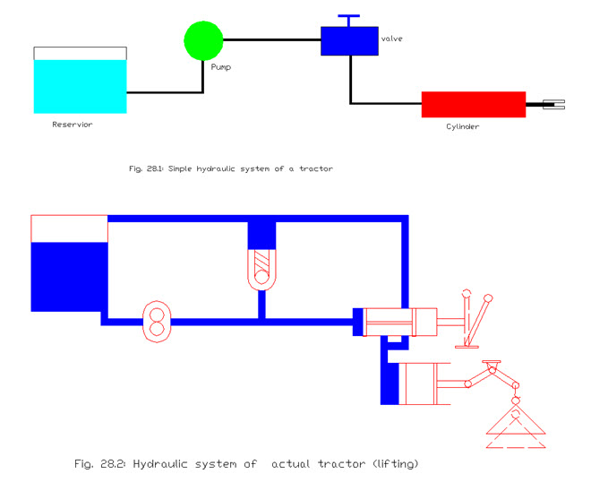
It is desired by a tractor to have more useful work performed at the field which led to the application of hydraulic system to accomplish various field tasks like tilling, harrowing, plowing, interculture, sowing etc. quickly. The most basic description of hydraulics is that it is the science of transmitting force or motion through a fluid. The hydraulic engineering through which we are well concerned with it is called hydrostatics, and deals with the ability to transmit force or motion through a fluid which is confined. Since the fluids are considered practically to be incompressible, hence these are preferred over gasses can be compressed. Flexibility of fluid make it the most advantageous in its use to transmit power. It can change shape, divide into parts, reunite as a whole, and fit exactly into the container of any shape. The liquid usually used in hydrostatics is hydraulic oil which gives the lubricating qualities also required by the moving components of the hydraulic system.
Components of a hydraulic system
Normally a hydraulic system is consisted of various components like sump, pump, safety valve, actuator, direction control valve, lines hoses, clamps etc. these are discussed here below-
Hydraulic pump
One type of fluid power transmission device is provided in the system which could be piston pump or gear pump or vane pump, etc. Reciprocating pumps are most efficient in hydraulic systems but rotary pumps are convenient to put in the system
Spur Gear pump
At present so many tractors are fitted with rotary pump like spur gear pump. The spur gear type pump is having a driving gear and a driven gear enclosed in a closely fitted housing. The rotary motion from crank shaft of tractor engine is transferred to the driving gear of the pump. Both the gears move in opposite directions and mesh at a point in the housing between the inlet and outlet ports. Both sets of teeth project outward from the center of the gears. As the teeth of the two gears separate, a partial vacuum forms and draws liquid through an inlet port into the housing and is trapped between the teeth of the two gears and the fluid is discharged through the housing to the discharge side. The liquid then pushed through the outlet as the rotating gears develop sufficient pressure. In this way the pressurize fluid flows through lines to a hydraulic ram or actuator.
Radial Piston Pump
Some of the Indian tractors are fitted with radial piston pump. Radial piston pumps are compact and reliable. These are capable of building high pressure, high volume and high speed. It is having a number of closely fitted parts and therefore wear is also considered to be more. In this type of pump , the pistons are arranged like wheel spokes in a short cylindrical block. There are many types of designs of radial piston pump . In this type of pump the pistons are arranged radially around an eccentric cam . The cam is a part of the main shaft. As the shaft rotates the pistons are reciprocated in the cylinders which are oriented radially . As the piston moves inwards the suction is caused and the space in the cylinder is filled with the fluid . When the piston moves outwards the fluid filled inside the cylinder forced outside the cylinder to the delivery side.
Lubrication
It is desired to have lubrication in the components of pump and actuator for smooth operation of the hydrostatic system. The pressure and flow of the fluid to the actuator which is ram cylinder begins when the pump moves the fluid away from its centered position by the tractors control apparatus. Lubrication of the various component increases as the system pressures rise by providing more fluid flow. Fluid which is utilized for lubrication should be an additional quantity so as not to affect the functioning of the system.
Pressure Control Valve (Relief Valve)
It is needed in the hydraulic system to have resistance in the flow of fluid which produces pressure and is necessary for the system to function. If the amount of resistance could not be controlled, it could become so high that the weakest component may burst. Therefore, the hydraulic circuit requires a relief valve to protect against excessive pressure cuased if any. The relief valve allows the fluid to be returned to the reservoir. The relief valves are utilized to limit the maximum operating pressure in the circuit. These are also called safety valves and protects the pump and other components from overloading, etc. Pressure relief valve is provided in the circuit such that one port is connected to the pressure line and the other port is connected to the the reservoir. There is a ball which is held on its seat with the spring force. The spring force can be changed by rotating the adjusting screw. When the circuit pressure at the valve inlet is less than the spring pressure , the ball remains on its seat and the valve is closed and no flow takes place through it. As the pressure in the circuit exceeds the adjusted spring force, the ball is forced off its seat and the valve is opened. Now the liquid flows from the pressure line through the valve to the reservoir. This diversion of flow continue till the. pressure decreases below the valve setting and hence the spring reseats the ball and the valve is again closed. In this way it prevents circuit and provide the safety.
Direction Control Valve
Valves which are used to control cylinder type actuators are known as the directional control valves. These may be check valve, rotary valve or spool valve, etc. Most of Indian tractors are fitted with spool type of valve. It may be open centre type or closed centre type depending upon type of circuit. Spool valve is a valve which controls the direction of hydraulic fluid flow. It consists of cylindrical spools which can block and open the channels in the hydraulic system. A spool valve can change the direction of flow of hydraulic fluid from a hydraulic pump to an actuator by blocking off the route of the fluid through which it takes place. Spool valve is consists of a spool which can move in the body of the valve and may have four or five ports. As in the figure below, a three way spool valve connected to an actuator of cylinder type. The fluid is applied to the port P of the valve and C of the cylinder, whereas, port T of the valve is connected to drain or return to the tank. Port A of the valve is connected to the B of the cylinder. Now if the spool is moved to right side with the help of lever, the high pressure fluid flows from port A and B. The moves to right due to pressure of fluid and displacing the fluid through port C and P. Now if the spool is moved to left, high pressure fluid comes into the cylinder through port C, and the piston moves to left causing the fluid into the tank via port B and A and T. Spool valve are generally manually operated in the tractors and are located at the right hand side of the operator.
Cylinder Type Actuator
A hydraulic system of tractor may have single or double acting cylinder . Most of our tractors are fitted with single acting cylinders . In this type of actuator the fluid is pumped into the cylinder forcing the piston outward. As the direction control valve is kept to neutral, the fluid get trapped and the load remained lifted. As the lever of this valve is moved to the left or right the trapped fluid gets away to sump. In single acting cylinder the piston braught back due to weight on the piston. But in the double acting cylinder the fluid can move both the sides of piton and applies the pressure to extend and retract the piston in the cylinder.
Sump
There is a rectangular shaped sump which store the fluid in it to move the piston for lifting the load. Hydraulic systems are generally operated by a liquid fluid being transmitted in the system components. A receiver tank, which stores energy for future use is basically a pressure vessel .It need a very large quantity of liquid fluid which is to be be stored and reused continuously as the circuit works. This tank is generally part of the tractor framework . In general reservoir design and its development is very important. The efficiency of a hydraulic circuit is greatly affected by tank design. Hence a hydraulic reservoir does much more than just provide a place to put fluid.
Lines and connectors
Tractor fluid lines are generally made up of metal tubing or flexible hose. Metal tubings are used where there are long runs are there. It is used to connect components like control valve and actuator or pump and safety valve etc. hoses are preferred where moving parts are there or where vibrations occurred. Metallic tubes are made up of steel ,or titanium etc. Various types of connectors may be used to connect the lines to the components.
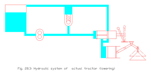
Automatic Draft and Depth Control (ADDC)
In some of the tractors a mechanism is provided so that required depth of field operation is maintained quite closely and simultaneously draft control is also allowed to work to have better traction. This is known as automatic draft and depth control.
Last modified: Thursday, 27 March 2014, 10:13 AM