Site pages
Current course
Participants
General
MODULE 1.
MODULE 2.
MODULE 3.
MODULE 4.
MODULE 5.
MODULE 6.
MODULE 7.
MODULE 8.
MODULE 9.
MODULE 10.
LESSON 16. Application of operated amplifier-inverting-non inverting- difference amplifier.
1) Inverting amplifier
The basic OP-AMP inverting amplifier is shown in Fig.16.1. The input voltage Vin is applied to the inverting input through the input resistor Rin. the non inverting input is grounded. The feedback resistor Rf is connected between the output and the inverting input.
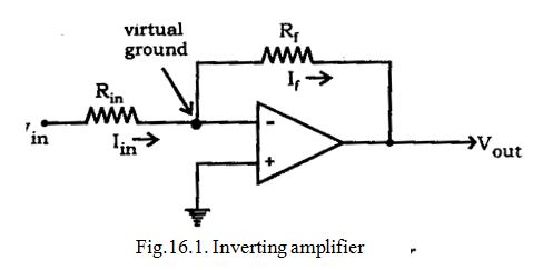
Since the input impedance of an op-amp is considered very high, no current can flow into or out of the input terminals. Therefore Iin must flow through Rf and is indicated by If (the feedback current). Since Rin and Rf are in series, then Iin = If. The voltage between inverting and non-inverting inputs is essentially equal to zero volt. Therefore, the inverting input terminal is also at 0 volt. For this reason the inverting input is said to be at virtual ground. The output voltage (Vout) is taken across Rf.
It can be proved that
If = - Vout / Rf
Since Iin = If then
Vin / Rin = -Vout / Rf
Rearranging the equation, we obtain
-Vout / Vin = Rf / Rin
Therefore the voltage gain of an inverting amplifier can be expressed as
Av = -Rf / Rin.
The amplifier gain is the ratio of Rf to Rin
Finally, the output voltage can be found by
Vout = -(Rf / Rin) x Vin
The output voltage is out of phase with the input voltage.
2) Non-inverting amplifier
The basic OP-AMP non-inverting amplifier is shown in Fig.16.2. The input signal Vin is applied to the non-inverting input terminal. The resistor Rin is connected from the inverting input to ground. The feedback resistor Rf is connected between the output and the inverting input.
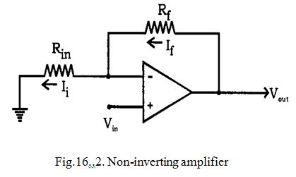
Resistors Rf and Rin form a resistive ratio network to produce the feedback voltage (VA) needed at the inverting input. Feedback voltage (VA) is developed across Rin. Since the potential at the inverting input tends to be the same as the non-inverting input (as pointed out with the description of virtual ground), Vin = VA.
Since VA = Vin, the gain of the amplifier can be expressed as
Av = Vout / VA
However, VA is determined by the resistance ratio of Rin and Rf ;
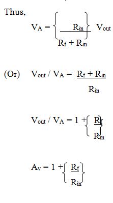
Finally, the output voltage can be found by, Vout = [1 + (Rf / Rin) Vin
It is seen that the input and output voltages are in phase.
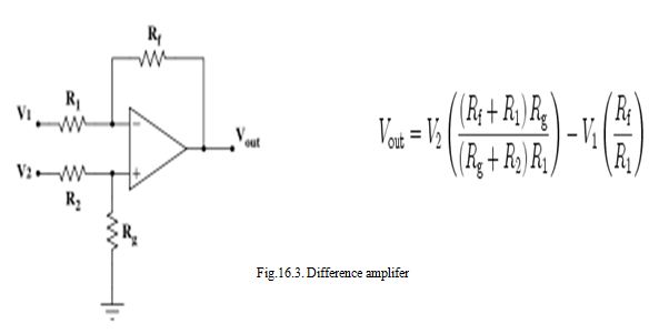
3) Difference amplifier:-
A differential amplifier is a type of an electronic amplifier that multiplies the difference between two inputs by some constant factor (the differentialgain). The basic OP-AMP Differential amplifier is shown in Fig.16.3.
By convention, the net difference of two voltages measured with respect to a common reference is called the differential-mode voltage, while the sum of the voltages, usually divided by two to give an average value, is called the common-mode voltage.
An ideal differential amplifier produces an output that is directly proportional to its differential-mode voltage.
The amplifier delivers zero output in response to common-mode
voltages.
The common-mode gain, the ratio of the output response of a real differential amplifier to the input signal applied equally to each input terminal, is a measure of this gain mismatch.
Differential amplification is very useful when the signal to be amplified exists in an electrically noisy environment. The most important requirement for a differential amplifier is that it be constructed with transistors with closely matched electrical characteristics .
Integrated circuits with amplifier transistors physically close to each other meet the required close matching requirement and are ideally suited for the production of differential amplifiers.
A differential amplifier is the input stage of operational amplifier or op-amps, and emitter coupled logic gates. Given two inputs Vin+ and Vin- , a practical differential amplifier gives an output Vout:
\[{V_{{\rm{out}}}}={A_{\rm{d}}}(V_{{\rm{in}}}^ + - V_{{\rm{in}}}^ - ) + {A_{\rm{c}}}\left( {{{V_{{\rm{in}}}^ + +V_{{\rm{in}}}^ - } \over 2}} \right)\]
The common mode rejection ratiois usually defined as the ratio between differential-mode gain and common-mode gain:
\[{\rm{CMRR}}={{{A_{\rm{d}}}} \over {{A_{\rm{c}}}}}\]
For a perfectly symmetrical differential amplifier with Ac = 0, the output voltage is given by,
\[{V_{{\rm{out}}}}={A_{\rm{d}}}(V_{{\rm{in}}}^ + -V_{{\rm{in}}}^ - )\]
Differential amplifiers are found in many systems that utilise negative feed back, where one input is used for the input signal, the other for the feedback signal.
A common arrangement for implementing a differential amplifier is the long-tailed pair, which is also usually found as the differential element in most op-amp integrated circuits
Applications of Difference amplifiers:-
When we have an input which has come from some distance and may have had some added interference. Using a pair of wires to send the signal we can then take the difference in potential between them as the signal and reject any ‘common mode’ voltages on both wires as being induced by interference. In feedback arrangements we can use the second input to control the behaviour of the amplifier. When we wish to combine two signals we can feed one into one transistor, and the second signal into the other.
Last modified: Saturday, 5 October 2013, 10:10 AM