Site pages
Current course
Participants
General
MODULE 1.
MODULE 2.
MODULE 3.
MODULE 4.
MODULE 5.
MODULE 6.
MODULE 7.
MODULE 8.
MODULE 9.
MODULE 10.
LESSON 5. Riveted Connections
5.1 INTRODUCTION
In engineering practice it is often required that two sheets or plates are joined together and carry the load in such ways that the joint is loaded. Many times such joints are required to be leak proof so that gas contained inside is not allowed to escape. A riveted joint is easily conceived between two plates overlapping at edges, making holes through thickness of both, passing the stem of rivet through holes and creating the head at the end of the stem on the other side. A number of rivets may pass through the row of holes, which are uniformly distributed along the edges of the plate. With such a joint having been created between two plates, they cannot be pulled apart. If force at each of the free edges is applied for pulling the plate apart the tensile stress in the plate along the row of rivet hole and shearing stress in rivets will create resisting force. Such joints have been used in structures, boilers and ships. The following are the usual applications for connection.
-
Screws ,
-
Pins and bolts,
-
Cotters and Gibs,
-
Rivets,
-
Welds.
Of these screws, pins, bolts, cotters and gibs are used as temporary fastening i.e., the components connected can be separated easily. Rivets and welds are used as permanent fastenings i.e., the components connected are not likely to require separation.
5.2 RIVETS
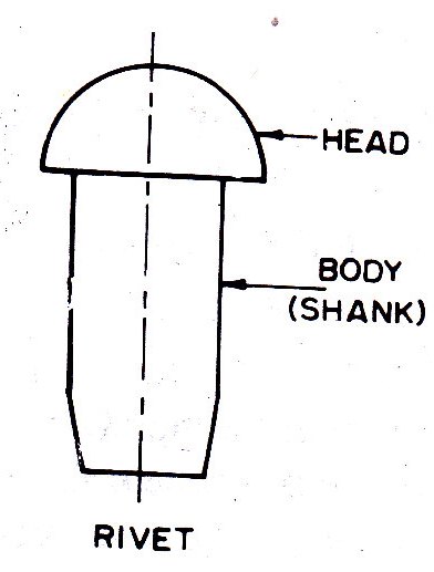
Rivet is a round rod which holds two metal pieces together permanently. Rivets are made from mild steel bars with yield strength ranges from 220 N/mm2 to 250 N/mm2. A rivet consists of a head and a body as shown in Fig 5.1. The body of rivet is termed as shank. The head of rivet is formed by heating the rivet rod and upsetting one end of the rod by running it into the rivet machine. The rivets are manufactured in different lengths to suit different purposes. The size of rivet is expressed by the diameter of the shank.
Holes are drilled in the plates to be connected at the appropriate places. For driving the rivets, they are heated till they become red hot and are then placed in the hole. Keeping the rivets pressed from one side, a number of blows are applied and a head at the other end is formed. When the hot rivet so fitted cools it shrinks and presses the plates together. These rivets are known as hot driven rivets. The hot driven rivets of 16 mm, 18 mm, 20 mm and 22 mm diameter are used for the structural steel works.
Some rivets are driven at atmospheric temperature. These rivets are known as cold driven rivets. The cold driven rivets need larger pressure to form the head and complete the driving. The small size rivets ranging from 12 mm to 22 mm in diameter may be cold driven rivets. The strength of rivet increases in the cold driving. The use of cold driven rivets is limited because of equipment necessary and inconvenience caused in the field.
The diameter of rivet to suit the thickness of plate may be determined from the following formulae:
-
Unwins’s formula d=6.05 t0.5
-
The French formula d=1.5 t + 4
-
The German formula d=(50 t – 2)0.5
Where d= nominal diameter of rivet in mm and t= thickness of plate in mm.
5.3 RIVET HEADS
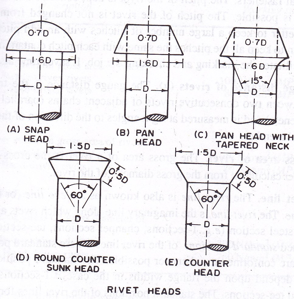
The various types of rivet heads employed for different works are shown in Fig. 5.2. The proportions of various shapes of rivet heads have been expressed in terms of diameter ‘D’ of the shank of rivet. The snap head is also termed as round head and button head. The snap heads are used for rivets connecting structural members. Sometimes it becomes necessary to flatten the rivet heads so as to provide sufficient clearance. A rivet head which has the form of a truncated cone is called a countersunk head. When a smooth flat surface is required, it is necessary to have rivets countersunk and chipped.
5.4 RIVET HOLES
The rivet holes are made in the plates or structural members by punching or drilling. When the holes are made by punching, the holes are not perfect, but taper. A punch damages the material around the hole. The operation known as reaming is done in the hole made by punching. When the hole are made by drilling, the holes are perfect and provide good alignment for driving the rivets. The diameter of a rivet hole is made larger than the nominal diameter of the rivet by 1.5 mm of rivets less than or equal to 25 mm diameter and by 2 mm for diameter exceeding 25 mm.
5.5 DEFINITIONS OF TERMS USED IN RIVETING
5.5.1 Nominal diameter of rivet (d):
The nominal diameter of a rivet means the diameter of the cold shank before driving.
5.5.2 Gross diameter of rivet (D):
The diameter of the hole is slightly greater than the diameter of the rivet shank. As the rivet is heated and driven, the rivet fills the hole fully. The gross or effective diameter of a rivet means the diameter of the hole or closed rivet. Strengths of rivet are based on gross diameter.
5.5.3 Pitch of rivet (p):
The pitch of rivet is the distance between two consecutive rivets measured parallel to the direction of the force in the structural member, lying on the same rivet line. Minimum pitch should not be less than 2.5 times the nominal diameter of the rivet. As a thumb rule pitch equal to 3 times the nominal diameter of the rivet is adopted. Maximum pitch shall not exceed 32 times the thickness of the thinner outside plate or 300 mm whichever is less.
5.5.4 Gauge distance of rivets (g):
The gauge distance is the transverse distance between two consecutive rivets of adjacent chains (parallel adjacent lines of fasteners) and is measured at right angles to the direction of the force in the structural member.
5.5.5 Gross area of rivet:
The gross area of rivet is the cross sectional area of a rivet calculated from the gross diameter of the rivet.
5.5.6 Rivet line:
The rivet line is also known as scrieve line or back line or gauge line. The rivet line is the imaginary line along which rivets are placed. The rolled steel sections have been assigned standard positions of the rivet lines. The standard position of rivet lines for the various sections may be noted from ISI Handbook No.1 for the respective sections. These standard positions of rivet lines are conformed to whenever possible. The departure from standard position of the rivet lines may be done if necessary. The dimensions of rivet lines should be shown irrespective of whether the standard positions have been followed or not.
5.5.7 Staggered pitch:
The staggered pitch is also known as alternate pitch or reeled pitch. The staggered pitch is defined as the distance measured along one rivet line from the centre of a rivet on it to the centre of the adjoining rivet on the adjacent parallel rivet line. One or both the legs of an angle section may have double rivet lines. The staggered pitch occurs between the double rivet lines.
5.6 TYPES OF JOINTS
Riveted joints are mainly of two types, namely, Lap joints and Butt joints.
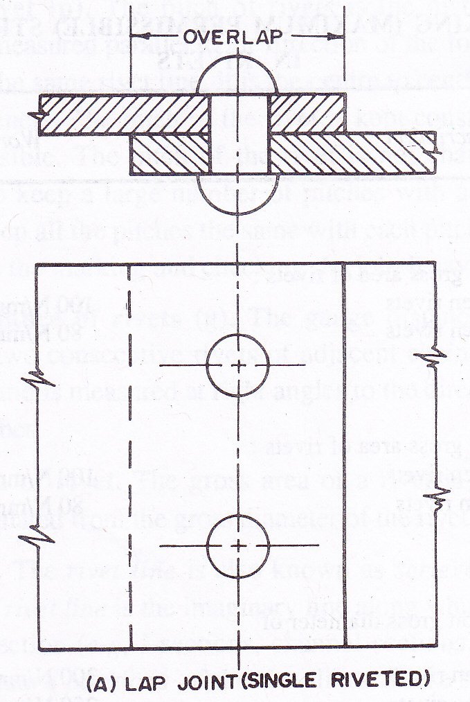
5.6.1 Lap Joint: Two plates are said to be connected by a lap joint when the connected ends of the plates lie in parallel planes. Lap joints may be further classified according to number of rivets used and the arrangement of rivets adopted. Following are the different types of lap joints.
-
Single riveted lap joint (Fig.5.3),
-
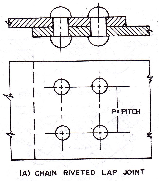
Double riveted lap joint:
a. Chain riveted lap joint (Fig.5.4) b. Zig-zag riveted lap joint (Fi.5.5)
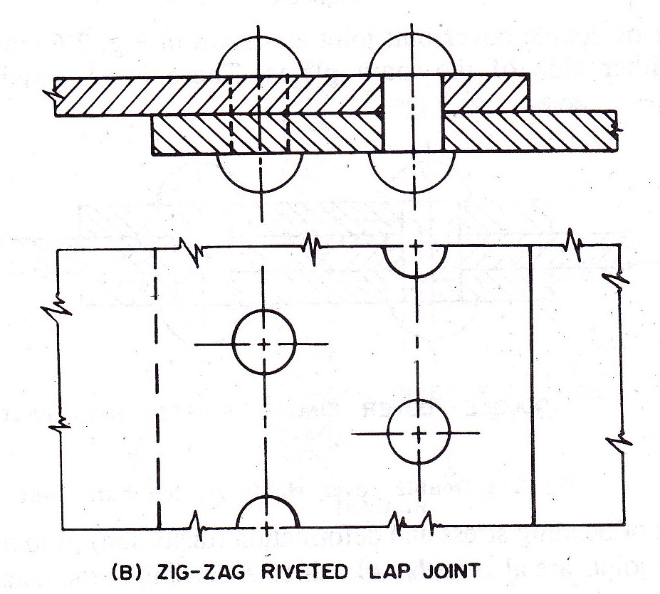
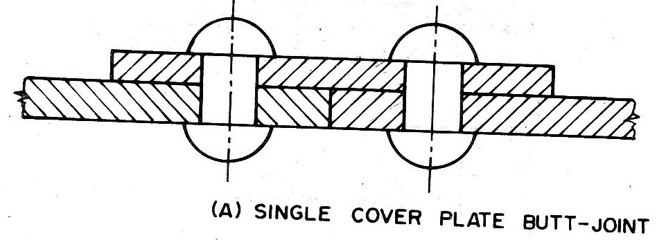
5.6.1 Butt Joint:
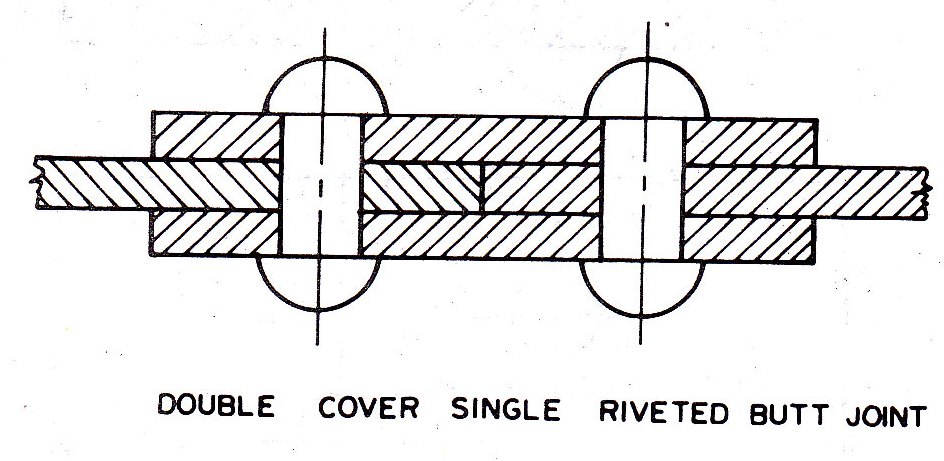
In a butt joint the connected ends of the plates lie in the same plane. The abutting ends of the plates are covered by one or two cover plates or strap plates. Butt joints may also be classified into single cover but joint, double cover butt joints. In single cover butt joint, cover plate is provided on one side of main plate (Fig.5.6). In case of double cover butt joint, cover plates are provided on either side of the main plate (Fig.5.7). Butt joints are also further classified according to the number of rivets used and the arrangement of rivets adopted.
-
Double cover single riveted but joint
-
Double cover chain riveted butt joint
-
Double cover zig-zag riveted butt joint
5.7 FAILURE OF A RIVETED JOINT
Failure of a riveted joint may take place in any of the following ways
-
Shear failure of rivets
-
Bearing failure of rivets
-
Tearing failure of plates
-
Shear failure of plates
-
Bearing failure of plates
-
Splitting/cracking failure of plates at the edges
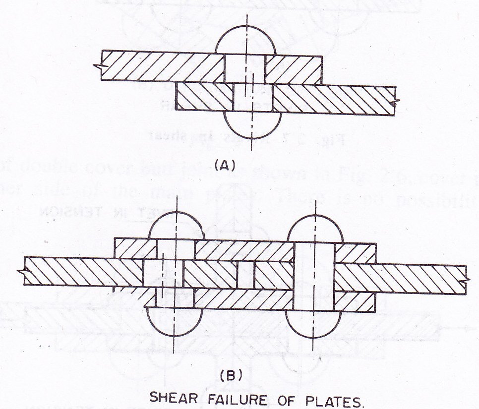
5.7.1 Shear failure of rivets :
Plates riveted together and subjected to tensile loads may result in the shear of the rivets. Rivets are sheared across their sectional areas. Single shear occurring in a lap joint and double shear occurring in but joint (Fig.5.8)
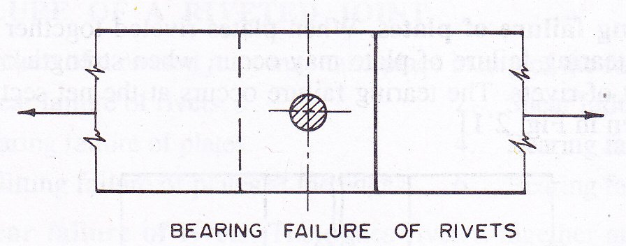
5.7.2 Bearing failure of rivets:
Bearing failure of a rivet occurs when the rivet is crushed by the plate (Fig.5.9)
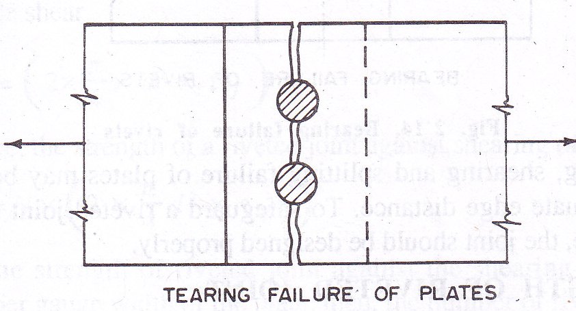
5.7.3 Tearing failure of plates :
When plates riveted together are carrying tensile load, tearing failure of plate may occur. When strength of the plate is less than that of rivets, tearing failure occurs at the net sectional area of plate (Fig.5.10)
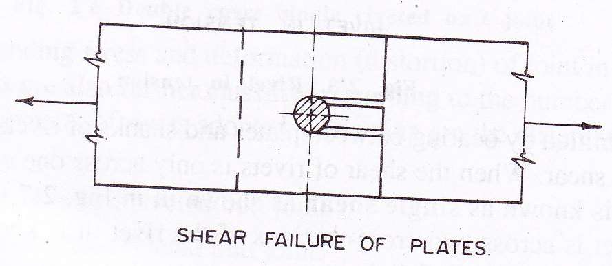
5.7.4 Shear failure of plates:
A plate may fail in shear along two lines as shown in Fig. 5.11. This may occur when minimum proper edge distance is not provided.
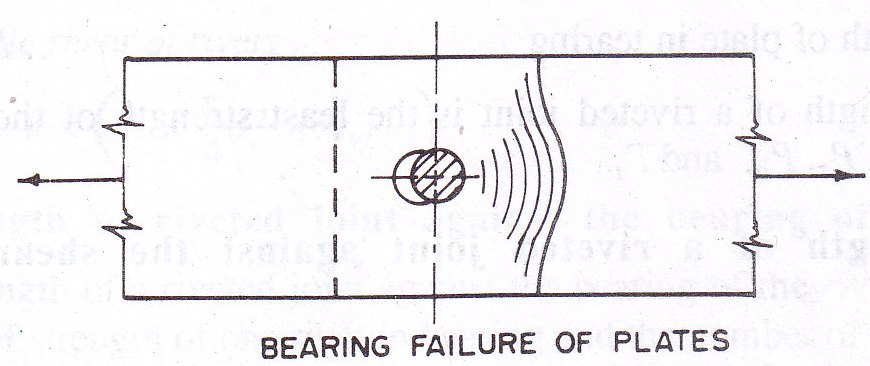
5.7.5 Bearing failure of plates:
Bearing failure of a plate may occur because of insufficient edge distance in the riveted joint. Crushing of plate against the bearing of rivet take place in such failure (Fig. 5.12)
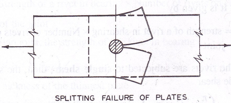
5.7.6 Splitting/cracking failure of plates at the edges:
This failure occurs because of insufficient edge distance in the riveted joint. Splitting (cracking) of plate as shown in Fig. 5.13 takes place in such failure.
Shearing, bearing and splitting failure of plates may be avoided by providing adequate proper edge distance. To safeguard a riveted joint against other modes of failure, the joint should be designed properly.
5.8 STRENGTH OF RIVETED JOINT
The strength of a riveted joint is determined by computing the following strengths:
-
Strength of a riveted joint against shearing - Ps
-
Strength of a riveted joint against bearing - Pb
-
Strength of plate in tearing - Pt
The strength of a riveted joint is the least strength of the above three strength.
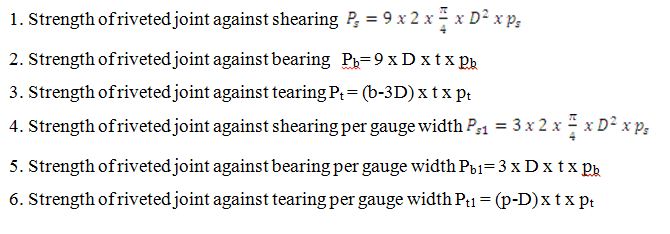
5.8.1 Strength of a riveted joint against shearing of the rivets:
The strength of a riveted joint against the shearing of rivets is equal to the product of strength of one rivet in shear and the number of rivets on each side of the joint. It is given by
Ps = strength of a rivet in shearing x number of rivets on each side of joint
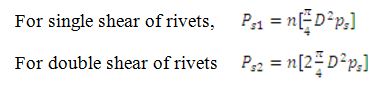
When the rivets are subjected to single shear, then the strength of one rivet in single shear
![]()
Therefore, the strength of a riveted joint against shearing of rivets = 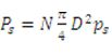
Where N=Number of rivets on each side of the joint; D=Gross diameter of the rivet; ps=Maximum permissible shear stress in the rivet(1025 ksc).
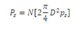
When the rivets are subjected to double shear, then the strength of one rivet in double shear = ![]() . Therefore, the strength of a riveted joint against double shearing of rivets,
. Therefore, the strength of a riveted joint against double shearing of rivets,
When the strength of riveted joint against the shearing of the rivets is determined per gauge width of the plate, then the number of rivets ‘n’ per gauge is taken in to consideration. Therefore,
5.8.2 Strength of riveted joint against the bearing of the rivets:
The strength of a riveted joint against the bearing of the rivets is equal to the product of strength of one rivet in bearing and the number of rivets on each side of the joint. It is given by,
Pb=Strength of a rivet in bearing x Number of rivets on each side of the joint
In case of lap joint, the strength of one rivet in bearing = D x t x pb
Where D= Gross diameter of the rivet; t=thickness of the thinnest plate; pb= maximum permissible stress in the bearing for the rivet (2360 ksc). In case of butt joint, the total thickness of both cover plates or thickness of main plate whichever is less is considered for determining the strength of a rivet in the bearing.
The strength of a riveted joint against the bearing of rivets Pb = N x D x t x pb
When the strength of riveted joint against the bearing of rivets per gauge widh of the plate is taken into consideration, then, the number of rivets ‘n’ is also adopted per gauge. Therefore,
Pb1 = n x D x t x pb
5.8.3 Strength of plate in tearing
The strength of plate in tearing depends upon the resisting section of the plate. The strength of plate in tearing is given by Pt = Resisting section x pt
Where pt is the maximum permissible stress in the tearing of plate (1500 ksc). When the strength of plate in tearing per pitch width of the plate is Pt1 = (p-D) x t x pt
The strength of a riveted joint is the least of Ps, Pb, Pt. The strength of riveted joint per gauge width of plate is the least of Ps1, Pb1, Pt1.
5.9. STRENGTH OF LAP AND BUTT JOINT
The strength of riveted lap and butt joint given in the Fig. 5.14 is summarized as follows:
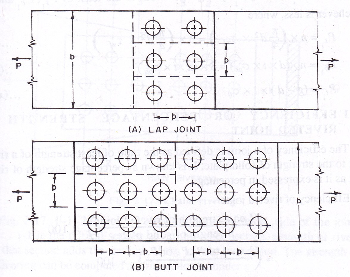
5.9.1 Strength of lap joint:
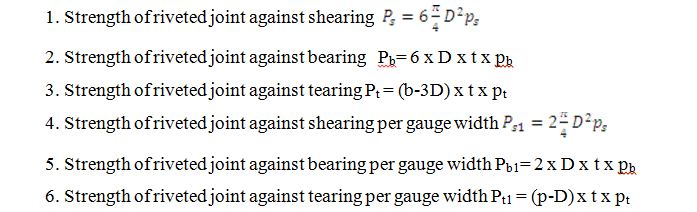
5.9.2 Strength of butt joint:
5.10 EFFICIENCY OR PERCENTAGE OF STRENGTH OF RIVETED JOINT
The efficiency of a joint is defined as the ratio of least strength of a riveted joint to the strength of solid plate. It is known as percentage strength of riveted joint as it is expressed in percentage.
Efficiency of riveted joint
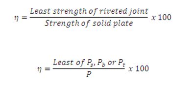
Where P is the strength of solid plate = b x t x pt
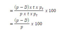
Efficiency per pitch width
5.11 RIVET VALUE
The strength of a rivet in shearing and in bearing is computed and the lesser is called the rivet value (R).
Last modified: Saturday, 5 October 2013, 5:21 AM