Site pages
Current course
Participants
General
MODULE 1.
MODULE 2.
MODULE 3.
MODULE 4.
MODULE 5.
MODULE 6.
MODULE 7.
MODULE 8.
MODULE 9.
MODULE 10.
LESSON 14. Design of Steel Beams
14.1 INTRODUCTION
The following points should be considered in the design of a beam.
-
Bending moment consideration: The section of the beam must be able to resist the maximum bending moment to which it is subjected.
-
Shear force consideration: The section of the beam must be able to resist the maximum shear force to which it is subjected.
-
Deflection consideration: The maximum deflection of a loaded beam should be within a certain limit so that the strength and efficiency of the beam should not be affected. Limiting the deflection within a safe limit will also prevent any possible damage to finishing. As per the I.S. code, generally the maximum deflection should not exceed 1/325 of the span.
-
Bearing stress consideration: The beam should have enough bearing area at the supports to avoid excessive bearing stress which may lead to crushing of the beam or the support itself.
-
Buckling consideration: The compression flange should be prevented from buckling. Similarly the web, the beam should also be prevented from crippling. Usually these failures do not take place under normal loading due to proportioning of thickness of flange and web. But under considerably heavy loads, such failures are possible and hence in such cases the member must be designed to remain safe against such failures
14.2 SHEAR AND BEARING STRESSES
When the beams are subjected to loads, then, these are also required to transmit large shear forces either at supports or at concentrated loads. For simply supported beams, the shear force is maximum at the supports. The values of shear force at the concentrated loads also remain large. Due to shear force, the shear stresses are setup along with the bending stresses at all sections of the beams. The shear stress at any point of the cross-section is given by
![]()
Where is the shear stress,
F = the shear force at cross-section,
Q = Static moment about the neutral axis of the portion of cross-sectional area beyond the location at which the stress is being determined.
I = Moment of inertia of the section about the neutral axis
t = Thickness of web (width of section at which the stress is being determined)
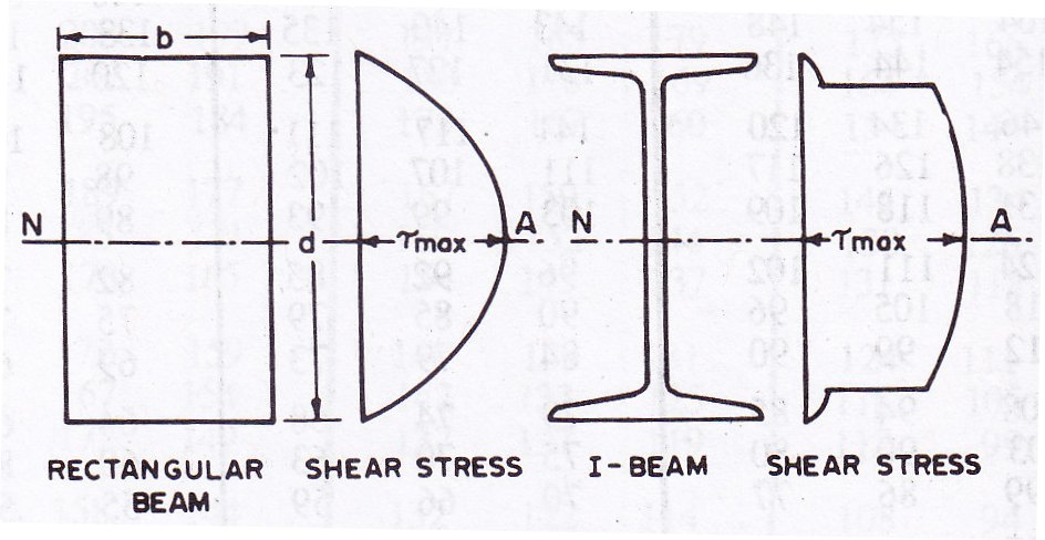
The distribution of shear stresses for rectangular section of beam and I-beam section are shown in Fig. 14.1. The maximum shear stress occurs at the neutral axis of the section. The maximum shear stress in a member having regard to the distribution of stresses in conformity with the elastic behavior of the member in flexure (bending) should not exceed the value of maximum permissible shear stress, τvm found as follows.
τvm=0.45fy
Where fy is the yield stress of structural steel to be used. It is to note that in the case of rolled beams and channels, the design shear is to be found as the average shear. The average shear stress for rolled beams or channels calculated by dividing the shear force at the cross-section by the gross-section of the web. The gross-cross-section of the web is defined as the depth of the beam or channel multiplied by its web thickness.
Average shear stress for rectangular beam is given by ![]()
Average shear stress for rectangular beam is given by ![]()
For rolled steel beams and channels, it is assumed that shear force is resisted by web only. The portion of shear resisted by the flanges is neglected. The average shear stress τva.cal, in a member calculated on the gross cross-section of web (when web buckling is not a factor) should not exceed in case of unstiffened web of the beam,
τva= 0.4 fy
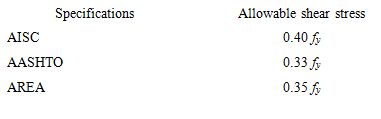
The allowable shear stress as per AISC, AASHTO and AREA specifications are as follows:
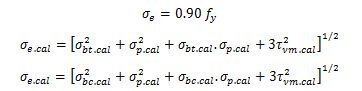
When the beams are subjected to co-existent bending stresses (tension or compression) and shear stress, then the equivalent stress, σe.cal is obtained from the following formula
![]()
The equivalent stress due to co-existent bending (tension or compression) and shear stresses should not exceed the maximum permissible equivalent stress σe found as under
![]()
When the bearing stress σp is combined with tensile or compressive bending and shear stresses under the most unfavourable conditions of loading, the equivalent stress σe.cal obtained as below should not exceed
σbc.cal, σbt.cal, τvm.cal and σp.cal are the numerical values of the co-existent bending (compression or tension), shear and bending stresses. When bending occurs about both the axes of the member, σbt.cal and σbc.cal should be taken as the sum of the two calculated fibre stresses, σe is the maximum permissible equivalent stress.
The bearing stress in any part of a beam when calculated on the net area of contact should not exceed the value of σp calculated as below
Where σp is the maximum permissible bearing stress and fy is the yield stress.
14.3 EFFECTIVE SPAN AND DEFLECTION LIMITATION
The effective span of a beam shall be taken as the length between the centres of the supports, except in cases where the point of application of the reaction is taken as eccentric to the support, then, it shall be permissible to take the effective span as the length between the assumed points of application of reaction.
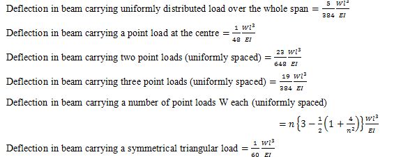
The stiffness of a beam is a major consideration in the selection of a beam section. The allowable deflections of beams depend upon the purpose for which the beams are designed. The maximum deflections for some standard cases are given below. In these formulae W is the total load on the beam in case of uniformly distributed load and each concentrated load in the case of concentrated loads.
The large deflections of beams are undesirable for the following reasons:
-
When the loads are primarily due to human occupants especially in the case of public meeting places, large deflections result in noticeable vibratory movement. This produces an uncomfortable sensation to the occupants.
-
The large deflections may result in cracking of ceiling plaster, floors or partition walls.
-
The large deflection indicate the lack of rigidity. It may cause vibrations and over-stresses under dynamic loads.
-
The large deflections may cause the distortions in the connections. The distortions cause secondary stresses.
-
The large deflections may cause poor drainage, which will lead to ponding of water and therefore increase the loads.
14.3.1 Limiting vertical deflection
The deflection of a member is calculated without considering the impact factor or dynamic effect of the loads causing the deflection. The deflection of a member shall not be such as to impair the strength or efficiency of the structure and lead to damage to finishing. Generally, the maximum deflection for a beam shall not exceed 1/325 of the span. This limit may be exceeded in cases where greater deflection would not impair the strength or efficiency of the structure or lead to damage to finishing. The deflection of the beams may be decreased by increasing the depth of beams, decreasing the span, providing greater and restraint or by any other means.
14.3.2 Limiting horizontal deflection
At the caps of columns in single storey buildings, the horizontal deflection due to lateral force should not ordinarily exceed 1/325 of the actual length ‘l’ of the column. This limit may be exceeded in cases where the grater deflection would not impair the strength and efficiency of the structure or lead to damage to finishing. According to AISE specifications, the deflections of beams and girders for live load and plastered ceiling should not exceed 1/360 of the span.
14.4 LATERALLY SUPPORTED BEAMS
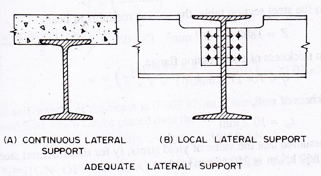
The laterally supported beams are also called laterally restrained beams. When lateral deflection of the compression flange of a beam is prevented by providing effective lateral support (restraint), the beam is said to be laterally supported. The effective lateral restraint is the restraint which produces sufficient resistance in a plane perpendicular to the plane of bending to restrain the compression flange of a beam from lateral buckling to either side at the point of application of the restraint. The concrete slab encasing the top flange, so that the bottom surface of the concrete slab is flush with the bottom of the top flange, is shown in Fig. 14.2.A. It provides a continuous lateral support to the top flange of the beam. When other beams frame at frequent intervals into the beam in questions as shown in Fig. 14.2.B, lateral support is provided at each point of connection but main beam should still be checked between the two supports.
In the laterally supported beams, the value of allowable bending compressive stress remains unaltered and the reduction in its value is not made. Bending comprehensive stress is taken equal to the allowable bending tensile stress, (σbc=σbt=0.66fy). The adequate lateral support is provided to safeguard against the lateral-torsional bucking. In case of doubt for adequate lateral support, the beams should be designed as laterally unsupported. In case the concrete slab holds the top flange (compression flange) of the beam from one side only, then, the lateral support is not credited. The concrete slab simply resting over the top flange of the beam without shear connectors also does not provide an lateral support. Sometimes, the plank or bar grating is attached to the top flange of beam by means of bolts. When the bolts are firmly fastened, then, they provide adequate lateral support temporarily. Even then, bolts have temporary nature of connections. It is possible that the bolts might be omitted or removed. As such, the top flange should not be considered laterally supported fully. The beams having lateral support from other members may buckle between points of lateral support. Therefore, the laterally unsupported length of beam is kept short.
14.5 DESIGN OF LATERALLY SUPPORTED BEAMS
The design of beams is generally governed by the maximum allowable bending stress and the allowable deflection. Its design is controlled by shear only when the spans are short and loads are heavy. The members are selected such that the sections are symmetrical about the plane of loading and the unsymmetrical bending and torsion are eliminated. The design of beams deals with proportioning of members, the determination of effective section modulus, maximum deflection and the shear stress. In general, the rolled steel sections have webs of sufficient thickness such that the criterion for design is seldom governed by shear. The following are the usual steps in design of laterally supported beams:
Step 1. For the design of beams, load to be carried by the beam, and effective span of the beam are known. The value of yield stress, fy for the structural steel to be used is also known. For the rolled steel beams of equal flanges as given in ISI Handbook no.1, the ratio of mean thickness of the compression flange (T=tf) to the thickness of web used to be less than 2.00. Also the ratio of the depth of web d1 to the thickness of web is also smaller than 85. The ends of compression flange of a laterally supported beam remain restrained against lateral bending (i.e., not free to rotate in plan at the bearings).
In the beginning of design, the permissible bending stress in tension, σbt or in compression, σbc may be assumed as 0.66 fy. The bending compressive stress, σbc and the bending tensile stress, σbt are equal for the laterally supported beam.
Step 2. The maximum bending moment M and the maximum shear force F in the beam are calculated. The required section modulus for the beam is determined as Z=(M/σbc)
Step 3. From the steel section tables, a rolled steel beam section, a rolled steel beam section, which provides more than the required section modulus is selected. The steel beam section shall have (D/T) and (l/ry) ratios more than 8 and 40 respectively. As such the trial section of beam selected may have modulus of section, Z more than that required. Some of the beam sections of different categories have almost the same value of the section modulus Z. It is necessary to note the weight of beam per meter length and the section modulus, Z. The beam section selected should be such that it has minimum weight and adequate section modulus, Z.
Step 4. The rolled steel beam section is checked for the shear stress. The average and maximum shear stresses should not exceed the allowable average and maximum values of shear stresses.
Step 5. The rolled steel beam is also checked for deflection. The maximum deflection should not exceed the limiting deflection.
ISI Handbook no.1 provides tables for allowable uniform loads on beams and channels used as flexural members with adequate lateral support for compression flange. The values of allowable uniform loads corresponding to respective effective spans are given for various beams and channel sections. For given span and total uniformly distributed load found, rolled beam or channel section may be selected from these tables. The rolled steel I-sections and wide flange beam sections are most efficient sections. These sections have excellent flexural strength and relatively good lateral strength for their weights.
Example 14.1 The effective length of compression flange of simply supported beam MB 500,@0.869 kN/m is 8 m. Determine the safe uniformly distributed load per meter length which can be placed over the beam having an effective span of 8 meters. Adopt maximum permissible stresses as per IS 800-1984. The ends of beam are restrained against rotation at the bearings.
Solution:
Step 1: Permissible bending stress
MB 500,@0.869 kN/m has been used as simply supported beam. The effective span of beam is 8 m. The effective length of compression flange is also 8 m.
From the steel section table, the section modulus of beam Z=1808.7 x 103 mm3
Mean thickness of compression flange tf =T= 17.2 mm
Thickness of web tw=10.2 mm
It is assumed that the value of yield stress, fy for the structural steel of MB 500,@0.869 kN/m is 250 N/mm2(MPa).

From IS: 800-1984, the maximum permissible bending stress, for above ratios (by linear interpolation) σbc=65.121 N/mm2(MPa)
Step 2: Load supported over beam
![]()
MB 500,@0.869 kN/m can resist maximum bending moment equal to moment of resistance. Therefore the maximum bending moment M=160.189 m-kN
Step 3: Load supported over beam
The effective span of the beam is 8 meters. Let w be the uniformly distributed load per meter length. The maximum bending moment, M for the beam occurs at the centre..
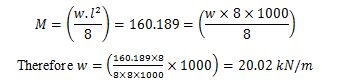
The self-weight of the beam is 0.869 kN/m. Therefore, the safe uniformly distributed load which can be placed over the beam (20.02-0.869)=19.15 kN.
Example 14.2 Design a simply supported beam to carry a uniformly distributed load of 44 kN/m. The effective span of beam is 8 meters. The effective length of compression flange of the beam is also 8 m. The ends of beam are not free to rotate at the bearings.
Design:
Step 1: Load supported, bending moment and shear force
Uniformly distributed load = 44 kN/m
Assume self weight of beam = 1.0 kN/m
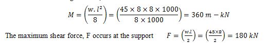
Total uniformly distributed load w= 45 kN/m
The maximum bending moment, M occurs at the centre
Step 2: Permissible bending stress
It is assumed that the value of yield stress, fy for the structural steel is 250 N/mm2 (MPa). The ratios (T/tw) and (d1/tw) are less than 2.0 and 85 respectively. The maximum permissible stress in compression or tension may be assumed as σbc = σbt = (0.66 x 250) = 165 N/mm2
![]()
The steel beam section shall have (D/T) and (l/ry) ratios more than 8 and 40 respectively. The trial section of beam selected may have modulus of section, Z more than that needed (about 25 to 50 per cent more).
Step 3: Trial section modulus
1.50 x 2181.82 x 103 mm3=3272.73 x 103 mm3
From steel section tables, try WB 600,@1.337 kN/m
Section modulus, Zxx=3540.0 x 103 mm3
Moment of inertia, Ixx=106198.5 x 104 mm4
Thickness of web, tw=11.2 mm
Thickness of flange, T=tf=21.3 mm
Depth of section, h=600 mm
Step 4: Check for section modulus
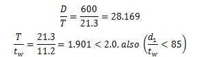
The effective length of compression flange of beam is 8 m.
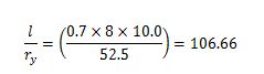
From IS: 800-1984, the maximum permissible bending stress σbc=118.68 N/mm2(MPa)
Section modulus required
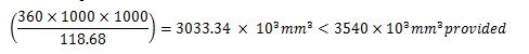
Further trial may give more economical section.
Step 5: Check for shear force
Average shear stress, ![]()
Permissible average shear stress
0.4 x fy = (0.4 x 250) = 100 N/mm2 > Actual average shear stress
Step 6: Check for deflection
Maximum deflection of the beam
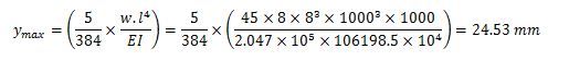
Allowable deflection ![]()
The maximum deflection is less than allowable deflection, hence the beam is safe. Provide WB 600,@1.337 kN/m
Last modified: Tuesday, 1 October 2013, 6:38 AM