Site pages
Current course
Participants
General
Module 1. Average and effective value of sinusoida...
Module 2. Independent and dependent sources, loop ...
Module 3. Node voltage and node equations (Nodal v...
Module 4. Network theorems Thevenin’ s, Norton’ s,...
Module 5. Reciprocity and Maximum power transfer
Module 6. Star- Delta conversion solution of DC ci...
Module 7. Sinusoidal steady state response of circ...
Module 8. Instantaneous and average power, power f...
Module 9. Concept and analysis of balanced polypha...
Module 10. Laplace transform method of finding ste...
LESSON 20. Polyphase System
20.1. Polyphase System
In an ac system it is possible to connect two or more number of individual circuits to a common polyphase source. Though it is possible to have any number of sources in a polyphase system, the increase in the available power is not significant beyond the three-phase system. The power generated by the same machine increases 41.4 per cent from single phase to two-phase, and the increase in the power is 50 per cent from single phase to three-phase. Beyond three-phase, the maximum possible increase is only seven per cent, but the complications are many. So, an increase beyond three-phase does not justify the extra complications. In view of not justify the extra complications. In view of this, it is only in exceptional cases where more than three phases are used. Circuits supplied by six, twelve and more phases are used in high power radio transmitter stations. Two-phase systems are used to supply two-phase servo motors in feedback control systems.
In general, a three-phase system of voltages (currents) is merely a combination of three single phase systems of voltages (currents) of which the three voltages (currents) differ in phase by 120 electrical degrees from each other in a particular sequence. One such three-phase system of sinusoidal voltages is shown in Fig.20.1.
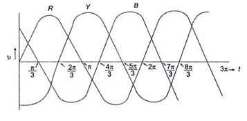
Fig. 20.1
20.2. Advantages of a Three-Phase System
It is observed that the polyphase, especially three-phase, system has many advantages over the single phase system, both from the utility point of view as well as from the consumer point of view. Some of the advantages are as under.
The power in a single phase circuit is pulsating. When the power factor of the circuit is unity, the power becomes zero 100 times in a second in a 50Hz supply. Therefore, single phase motors have a pulsating torque. Although the power supplied by each phase is pulsating, the total three-phase power supplied to a balanced three-phase circuit is constant at every instant of time. Because of this, three-phase motors have an absolutely uniform torque.
To transmit a given amount of power over a given length, a three-phase transmission circuit requires less conductor material than a single-phase circuit.
In a given frame size, a three-phase motor or a three-phase generator produces more output than its single phase counterpart.
Three-phase motors are more easily started than single phase motors. Single phase motors are not self-starting, whereas three-phase motors are.
In general, we can conclude that the operating characteristics of a three-phase apparatus are superior than those of a similar single phase apparatus. All three-phase machines are superior in performance. Their control equipment’s are smaller, cheaper, lighter in weight and more efficiency. Therefore, the study of three phase circuits is of great importance.
20.3. Generation of Three-Phase Voltages
Three-phase voltages can be generated in a stationary armature with a rotating field structure, or in a rotating armature with a stationary field as shown in Fig.20.2 (a) and (b).
Single phase voltages and currents are generated by single phase generators as shown in Fig. 20.3 (a). The armature (here a stationary armature) of such a generator has only one winding, or one set of coils. In a two-phase generator the armature has two distinct winding, or two sets of coils that are displaced 900 (electrical degrees) apart, so that the generated voltages in the two phases have 900 phase displacement as shown in Fig. 20.3 (b). Similarly, three-phase voltages are generated in three separate but identical sets of winding or coils that are displaced by 120 electrical degrees in the armature, so that the voltages generated in them are 1200 apart in time phase. This arrangement is shown in Fig. 20.3 (c). Here RR’ constitutes one coil (R-phase); YY’ another coil (Y-phase), and BB’ constitutes the third phase (B-phase). The field magnets are assumed in clockwise rotation.
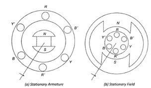
Fig. 20.2
The voltage generated by a three-phase alternator is shown in Fig.20.3 (d). The three voltages are of the same magnitude and frequency, but are displaced from one another by 1200. Assuming the voltages to be sinusoidal, we can write the equations for the instantaneous values of the voltages of the three phases. Counting the time from the instant when the voltage in phase R is zero. The equations are

Fig.20.3
VRR’ = Vm sin wt
Vyy’ = Vm sin (wt – 1200)
VBB’ = Vm sin (wt – 2440)
At any given instant, the algebraic sum of the three voltages must be zero.
20.4. Phase Sequence
Here the sequence of voltages in the three phases are in the order VRR’ - Vyy’ - VBB’ and they undergo changes one after the other in the above mentioned order. This is called the phase sequence. It can be observed that this sequence depends on the rotation of the field. If the field system is rotated in the anticlockwise direction, then the sequence of the voltages in the three-phases are in the order VRR’ - Vyy’ - VBB’; briefly we say that the sequence is RBY. Now the equations can be written as
VRR’ = Vm sin wt
VBB’ = Vm sin (wt – 2440)
Vyy’ = Vm sin (wt – 1200)
20.5 Inter connection of three –phase sources and loads
20.5.1 Inter connection of three –phase sources
In a three-phase alternator, there are three independent phase windings or coils. Each phase or coil has two terminals, viz. start and finish. The end connections of the three sets of the coils may be brought out of the machine, to form three separate single phase sources to feed three individual circuits as shown in Fig. 20.4 (a) and (b).
The coils are inter-connected to form a wye (Y) or delta (D) connected three-phase system to achieve economy and to reduce the number of conductors, and thereby, the complexity in the circuit. The three-phase sources so obtained serve all the functions of the three separate single phase sources.
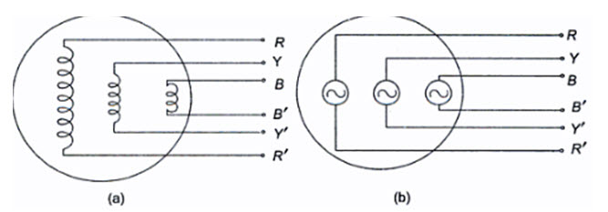
Fig.20.4
Wye or Star-Connection
In this connection, similar ends (start or finish) of the three phases are joined together within the alternator a shown in Fig.20.5. The common terminal so formed is referred to as the neutral point (N), or neutral terminal. Three lines are run from the other free ends (R, Y, B) to feed power to the three-phase load.
Figure 20.5 represents a three-phase, four-wire, star-connected system. The terminals R,Y and B are called the line terminals of the source. The voltage between any line and the neutral point is called the phase voltage (VRN’ VYN and VBN), while the voltage between any two lines is called the line voltage (VRY’ VYB and VBR). The currents flowing through the phases are called the phase currents, while those flowing in the lines are called the line currents. If the neutral wire is not available for external connection, the system is called a three-phase, three-wire, star-connected system. The system so formed will supply equal line voltages displaced 1200 from one another and acting simultaneously in the circuit like three independent single phase sources in the same frame of a three-phase alternator.
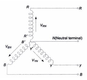
20.5
Delta or Mesh-Connection
In this method of connection the dissimilar ends of the windings are joined together, i.e. R’ is connected to Y, Y’ to B and B’ to as shown in Fig. 20.6.
The three line conductors are taken from the three junctions of the mesh or delta connection to feed the three-phase load. This constitutes a three-phase, three-wire, delta-connected system. Here there is no common terminal; only three line voltages VRY’ VYB and VBR are available.
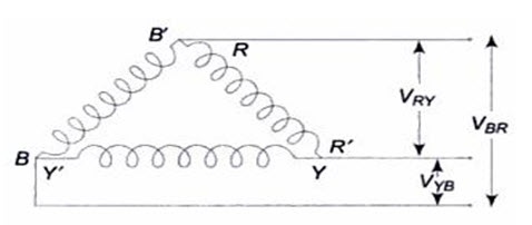
Fig.20.6
These line voltages are also referred to as phase voltages in the delta connected system. when the sources are connected in delta, loads can be connected only across the three line terminals, R, Y and B. In general, a three-phase source, star or delta, can eb either balanced or unbalanced. A balanced three-phase source is one in which the three individual sources have equal magnitude, with 1200 phase difference as shown in Fig. 20.3 (d).
Interconnection of Loads
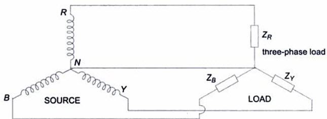
The primary question in a star or delta-connected three-phase supply is how to apply the load to the three-phase supply. An impedance, or load, connected across any two terminals of an active network (source) will draw power from the source, and is called a single phase load. Like alternator phase windings, load can also be connected across any two terminals, or between neutral and neutral terminal (if the source is star-connected). Usually the three-phase load impedances are connected in star or delta formation, and then connected to the three-phase source as shown in Fig.20.7 (a) and 20.7 (b).
(A)
(B)
20.7 (b)
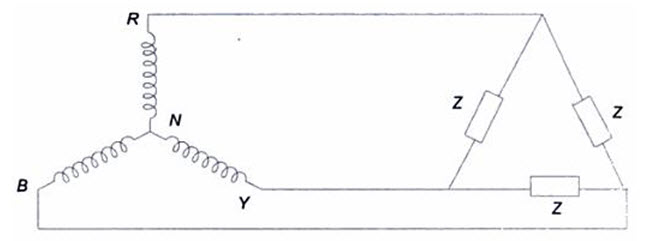
Figure 20.7 (a) represents the typical inter-connections of loads and sources in a three-phase star system, and is of a three-phase four wire system. A three line and neune -phase star connected load is connected to a three-phase star-connected source, terminal to terminal, and both the neutrals are joined with a fourth wire. Figure 20.7 (b) is a three-phase, three-wire system. a three-phase, delta connected load is connected to a three-phase star-connected source, terminal to terminal, as shown in Fig.20.7 (b). When either source or load, or both are connected in delta, only three wires will suffice to connect the load to source.
Just as in the case of a three-phase source, a three-phase load can be either balanced or unbalance. A balanced three-phase load is one in which all the branches have identical impedances, i.e. each impedance has the same magnitude and phase angle. The resistive and reactive components of each phase are equal. Any load which does not satisfy the above requirements is said to be an unbalanced load.
20.6. Star to Delta and Delta to Star Transformation
While dealing with currents and voltages in loads, it is often necessary to convert a star load to delta load, and vice-versa. The delta (Δ) connection of resistances can be replaced by an equivalent start (Y) connection and vice-versa. Similar methods can be applied in the case of networks containing general impedances in complex from. So also with ac, where the same formulae hold good, except that resistances are replaced by the impedances. These formulae can be applied even if the loads are unbalanced. Thus, considering Fig. 20.8 (a), star load can be replaced by an equivalent delta-load with branch impedances as shown.
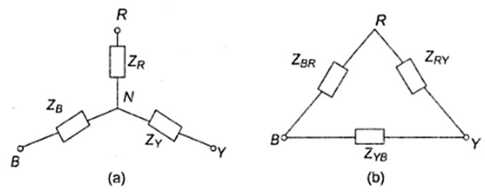
Fig. 20.8
Delta impedances, in terms of star impedances, are
\[{Z_{RY}}={{{Z_R}{Z_Y} + {Z_Y}{Z_B} + {Z_B}{Z_R}} \over {{Z_B}}}\]
\[{Z_{YB}}={{{Z_R}{Z_Y} + {Z_Y}{Z_B} + {Z_B}{Z_R}} \over {{Z_R}}}\]
and \[{Z_{BR}}={{{Z_R}{Z_Y} + {Z_Y}{Z_B} + {Z_B}{Z_R}} \over {{Z_Y}}}\]
The converted network is shown in Fig.20.8 (b). Similarly, we can replace the delta load of Fig.20.9 (b) by an equivalent star load with branch impedances as
\[{Z_R}={{{Z_{RY}}{Z_{BR}}} \over {{Z_{RY}} + {Z_{YB}} + {Z_{BR}}}}\]
\[{Z_Y}={{{Z_{RY}}{Z_{YR}}} \over {{Z_{RY}} + {Z_{YB}} + {Z_{BR}}}}\]
and \[{Z_B}={{{Z_{BR}}{Z_{YB}}} \over {{Z_{RY}} + {Z_{YB}} + {Z_{BR}}}}\]
It should be noted that all impedances are to be expressed in their complex form.
Balanced Star-Delta and Delta-Star Conversion
If the three-phase load is balanced, then the conversion formulae in Section 20.6 get simplified. Consider a balanced star-connected load having an impedance Z1 in each phase as shown in Fig.20.9 (a).
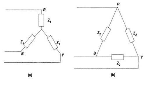 Fig.20.9
Let the equivalent delta-connected load have in impedance of Z2 in each phase as shown in Fig.20.9 (b). Applying the conversion formulae from Section 20.6 for delta impedances in terms of star impedances, we have
Z2 = 3Z1
Similarly, we can express star impedances in terms of delta Z1 = Z2/3.
Last modified: Thursday, 26 September 2013, 10:52 AM