Site pages
Current course
Participants
General
MODULE 1. Electro motive force, reluctance, laws o...
MODULE 2. Hysteresis and eddy current losses
MODULE 3. Transformer: principle of working, const...
MODULE 4. EMF equation, phase diagram on load, lea...
MODULE 5. Power and energy efficiency, open circui...
MODULE 6. Operation and performance of DC machine ...
MODULE 7. EMF and torque equations, armature react...
MODULE 8. DC motor characteristics, starting of sh...
MODULE 9. Polyphase systems, generation - three ph...
MODULE 10. Polyphase induction motor: construction...
LESSON 1. Electro motive force, reluctance and laws of magnetic circuits
Production of Magnetic Field: When the current i amperes flows through a conductor, the magnetic flux is around as explained by right hand cork-screw rule. To determine the direction of flux created due flow of current in a conductor as wound round the path, consider the diagram in figure 1.1. The flux is along the central axis of the coil (solenoid coil ) as shown.
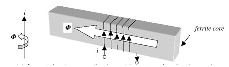
Fig. 1.1: Law relating the current direction and the resultant flux direction - cork-screw rule
Production of Magnetic Field
Consider the magnetic core shown in the diagram of Figure 1.2. It has a winding carrying a current of i amperes and N turns. It generates a magneto motive force (MMF) F of N.i ampere (A).
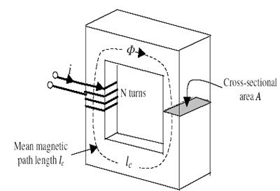
Fig. 1.2: A simple magnetic Core
Since the number of turns, N is dimensionless, the SI unit for MMF is just ampere, denoted by A. Magnetomotive Force (mmf drives the magnetic flux through the circuit and is analogous to emf in the electrical circuit. The magneto motive force of a circuit is measured by the work done in carrying a unit north pole through the entire circuit. The MMF creates a magnetic field in core having a field intensity of H ampere-turns / meter along the length of the magnetic path. Upon integrating the magnetic field intensity along the magnetic path, we get,
∫ H dl = N.i ampere (A) (1)
The above is the Ampere's law governing the production of a magnetic field by a current carrying coil. If the path of integration is the mean path length of the core lc, Ampere’s law becomes;
H.lc = N.i (2)
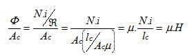
This MMF ‘F’ drives through the magnetic core, a flux Φ Webers. The flux Φ can be related as:
![]() (3)
(3)
The term R refers to reluctance of the magnetic core. The MMF has to drive the flux Φ against this reluctance R. The reluctance of the magnetic core may be given by the following expression:
 (4)
(4)
Where lc refers to the mean length of the magnetic path in meters, Ac refers to the cross-sectional area of the flux path in meter2 and the term µ refers to the permeability of the magnetic material of the core.
The unit for R is 1/henry or 1/H. The unit for µ is H/m. The permeability of free space or air is µ 0 and is given by;
µ 0 = 4 Пx10-7 H/m (5)
Remember that each ferromagnetic material has its own relative permeability (µr) and can be found from manufacturer where;
µ = µ 0 x µr (6)
Relative permeability is a convenient way to compare the magnetizability of different materials. For Example, the steels used in modern machines have relative permeability in the range 2000 to 6000. This means that, for a given amount of current, 2000 to 6000 times more flux is established in a piece of steel than in a corresponding area of air. Obviously, the metal in a transformer or a motor core may play an extremely important role in increasing and concentrating the magnetic flux in the device.
Since the permeability of iron is much higher than that of Air, a major portion of the flux in configuration, likes that of Figure 1.2, remains inside the core instead of traveling through the surrounding Air, which has lower permeability. The small portion of flux that does not travel through the iron core, but travels through Air path is called leakage flux. Treatment of leakage flux is very important in transformer and motors.
The flux density B may be defined as
![]() (7)
(7)
Flux Density (B) is the number of webers or of lines of induction per unit area, the area being taken at right angles to the direction of the flux.
Resolving Φ in the above equation using equation (3) and (4) we get,
 (8)
(8)
The unit of the flux density is Weber/ meter2, known as tesla (T). Thus, alternatively, the flux determined in (3) may be found as below
![]() (9)
(9)
where dS is the differential unit of the cross-sectional area. If the flux density vector B is perpendicular to a plane of area Ac, and if the flux density B is constant throughout the area, then this equation reduces to
Φ = B.Ac (10)
Thus, the total flux in the core in Figure 1.2 due to the current i in the winding is
![]() (11)
(11)
Based on the analogy between magnetic circuits and dc resistive circuits, Table below summarizes the corresponding quantities. Further, the laws of resistances in series and parallel also hold for reluctances. Analogy with dc Resistive Circuits.
|
DC Resistive Circuit |
Magnetic Circuit |
|
Current I (A) |
Flux φ (Wb) |
|
Voltage V (V) |
Magnetomotive force (mmf) F |
|
Resistance R = l/rA |
Reluctance = l/µA (H−1 ) |
|
Conductivity r (S/m) |
Permeability µ ( H/m) |
|
I = V /R |
φ = F / Reluctance |
|
Current density J = I/A (A/m2) |
Flux density B = φ/A (Wb/m2) |
Magnetic Field Intensity, Relative Permeability and Reluctance
We define a new fundamental field quantity, the magnetic field intensity H, such that
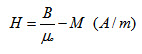 (12)
(12)
The Ampere law and other laws helps us to understand that magnetic flux behaves in the same manner as the current flowing in closed loops and many of magnetic circuits applications are of different shapes, sizes, and may come in unified or composite ferromagnetic materials.
Ampere’s circuital law: the circulation of the magnetic field intensity around any closed path is equal to the free current flowing through the surface bounded by the path. Ampere’s circuital law is most useful on determining the magnetic field caused by a current when cylindrical symmetry exists. When the magnetic properties of the medium are linear and isotropic, the magnetization is directly proportional to the magnetic field intensity:
M = χm H,
where χmis called magnetic susceptibility.
Last modified: Saturday, 1 March 2014, 11:59 AM