Site pages
Current course
Participants
General
MODULE 1. Electro motive force, reluctance, laws o...
MODULE 2. Hysteresis and eddy current losses
MODULE 3. Transformer: principle of working, const...
MODULE 4. EMF equation, phase diagram on load, lea...
MODULE 5. Power and energy efficiency, open circui...
MODULE 6. Operation and performance of DC machine ...
MODULE 7. EMF and torque equations, armature react...
MODULE 8. DC motor characteristics, starting of sh...
MODULE 9. Polyphase systems, generation - three ph...
MODULE 10. Polyphase induction motor: construction...
LESSON 3. Hysteresis and eddy current losses
Before explaining hysteresis and eddy currents, let us look at some basic definitions and laws that govern electro magnetic induction
Lorentz Force
– The force on a moving charge in a magnetic field is proportional to the charge, velocity, and magnetic field strength.
Lenz’s Law
–The induced currents in a conductor are in such a direction as to oppose the change in magnetic field that produces them
Ampere’s Law
–The line integral of the magnetic field intensity around a closed path is equal to the algebraic sum of the currents flowing through the area enclosed by the path.
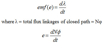
Faraday’s law:
–Currents can be induced in wires by changing magnetic fields.
A time-varying magnetic field induces an electromotive force that produces a current in a closed circuit. This current flows in a direction such that it produces a magnetic field that tends to oppose the changing magnetic flux of the original time varying field.
Mathematically
1. Time varying flux linking stationary path – transformer
2. Relative motion between steady flux and stationary path – synchronous generator under no-load conditions
3. A combination of previous two cases – induction
The above 3 points means that, voltage production in the above equations are dependent on flux, which is produced by AC flowing current. So if the closed path is a winding of transformer, then the flux will be produced and it can be received by another closed path windings and that what developed the transformer principle.
If coil connected to voltage source,V , current i will flow as shown in figure 2.1.
- Current will produce magnetic flux, Φ
- Total flux linkages of the coil containing N turns λ = NΦ
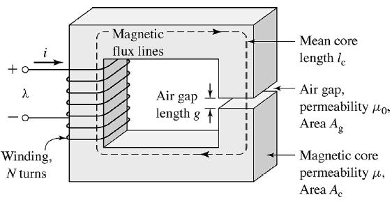
Fig. 2.1 Magnetic circuit
Magnetization curve or B-H curve
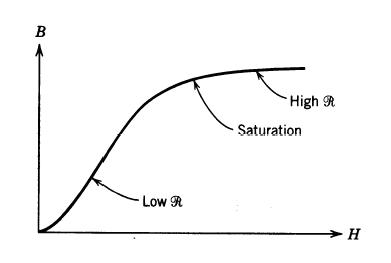
Fig. 2.2 Effect of reluctance on typical magnetization
• at low magnetic field intensity magnetic flux density increases almost (Fig. 2.2)linearly
• at higher values of magnetic field intensity the change of magnetic flux density is nonlinear - reaches saturation (Fig. 2.2)
Magnetic behavior of ferromagnetic materials
• The magnetic permeability (µ) is not constant as shown in figure 2.3:
B = Hm
Devices such as transformers have to operate in the linear (non-saturated) region.
B-H curve can be divided into regions; residual magnetism, linear portion, knee and saturation region.
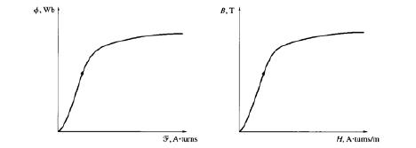
Fig. 2.3 B-H as it relates to Φ-I
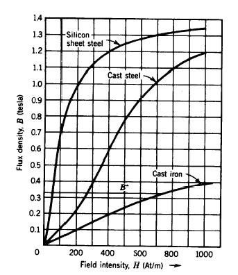
Fig. 2.4 Different B-H curves of some ferromagnetic materials
Each ferromagnetic material (Fig. 2.4) has its B-H- curve or magnetization curve.
Last modified: Tuesday, 1 October 2013, 7:06 AM