Site pages
Current course
Participants
General
MODULE 1. Electro motive force, reluctance, laws o...
MODULE 2. Hysteresis and eddy current losses
MODULE 3. Transformer: principle of working, const...
MODULE 4. EMF equation, phase diagram on load, lea...
MODULE 5. Power and energy efficiency, open circui...
MODULE 6. Operation and performance of DC machine ...
MODULE 7. EMF and torque equations, armature react...
MODULE 8. DC motor characteristics, starting of sh...
MODULE 9. Polyphase systems, generation - three ph...
MODULE 10. Polyphase induction motor: construction...
LESSON 11. Operation and performance of DC machine (generator and motor)
Generator
Definition.—A generator is a machine which converts mechanical energy into electrical energy. This is accomplished by means of an armature carrying conductors upon its surface, acting in conjunction with a magnetic field. Electrical power is generated by the relative motion of the armature conductors and the magnetic field. In the direct-current generator the field is usually stationary and the armature rotates. In most types of alternating-current generators the armature is stationary and the field rotates. Either the armature or the field is driven by mechanical power applied to its shaft.
Generated Electromotive Force- If the flux linking a coil is varied in any way, an
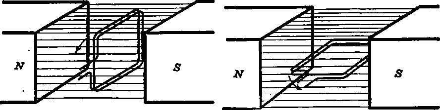
(a) Maximum lines passing through coil (b) No lines passing through coll
Fig. 6.1 Simple coil rotating in a magnetic field.
electromotive force is induced in the turns of the coil. The action of the generator is based on this principle. The flux linking the armature coils is varied by the relative motion of the armature and field.
A coil revolves in a uniform magnetic field produced by a north and a south pole. In Fig. 6.1 (a) the coil is perpendicular to the magnetic field and in this position the maximum possible flux links the coil. If the coil be rotated counter-clockwise a quarter of a revolution, it will lie in the position shown in Fig. 6.1 (b). As the plane of the coil is parallel to the flux no lines link the coil in this position. Therefore, in a quarter revolution the flux which links the coil has been decreased by t lines. The average voltage induced in the coil during this period is, therefore,
e = Nj(10-8) /t
where, N is the number of turns in the coil and t the time required for a quarter revolution. But t = 1/4R where R = the revolutions per second. Therefore, the average voltage during a quarter revolution is e = 4NRj(10-8) volts
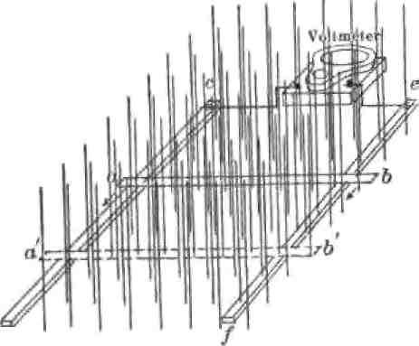
Fig. 6.2. Conductor cutting a uniform magnetic field
The generation of electromotive force in a moving coil of this type, which is similar to those used in dynamos, may also be analyzed by considering the total electromotive force as being due to the sum of the electromotive forces generated in each side of the coil. The electromotive force of one turn is the sum of the electromotive forces in each conductor forming the sides of the turn, since these conductors are connected in series by the end connections of the turn. The individual electromotive forces are then considered as being generated in the conductor rather than induced in the coil.
Consider the conductor ab, free to slide along the two metal rails cd Fig. 6.2. The rails are connected at one end ‘ce’ by a voltmeter. A magnetic field having a density of B lines per sq. cm. passes perpendicularly through the plane of the rails and conductor. Let the conductor ab move at a uniform velocity to the position a'b’. While this movement is taking place, the voltmeter will indicate a certain voltage.
The electromotive force in volts generated by a single conductor which cuts a magnetic field is
e = Blv (10-8) (93)
where B, I and v are mutually perpendicular. B is the flux density of the field in gausses, I the length of conductor in centimeters, and v the velocity of the conductor in.centimeters per second.
That the electromotive force induced by a change of the flux linked with a coil is the same as that obtained by considering the emf generated by the cutting of magnetic lines by the conductor which make up the coil may be illustrated by a concrete example. Let the flux have a density of 100 lines per cm2. The distance ab is 30 cm. and aa’ is 20 cm. The conductor ab moves at a uniform velocity to position a'b’ in 0.1 second. What is the electromotive force across ‘ce’?
The change of flux linking the coil is:
j = 30 X 20 X 100 = 60,000 lines.
This change occurs in 0.1 second and v = 20/0.1= 200 cm s-1.
e = 100 X 30 X 200 X 10~* = 0.006 volt.
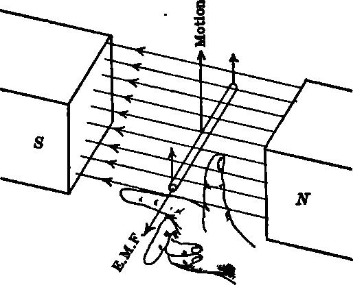
Fig. 6.3 Fleming's right-hand rule: Fore finger along lines of force; Thumb in direction of motion; Middle finger gives direction of induced emf.
Direction of Induced Electromotive Force: Fleming's Right-hand Rule definite relation exists among the direction of the flux, the direction of motion of the conductor and the direction of the electromotive force in the conductor just as a definite relation exists between the direction of current and of the flux which it produces.
If the fore-finger points along the lines of flux and the thumb in the direction of motion of the conductor, the middle finger will point in the direction of the induced electromotive force.
Voltage generated by the revolution of a coil. A coil of a single turn is shown in Fig.6.4 below. The coil rotates in a counter-clockwise direction at a uniform speed in a uniform magnetic field. As the coil assumes successive positions, the electromotive force induced in it changes. When it is in position (1) the electromotive force generated is zero, for in this position neither conductor is cutting magnetic lines, but rather is moving parallel to these lines. When the coil reaches position (2), (shown dotted) its conductors are cutting across the lines obliquely and the electromotive force has a value indicated
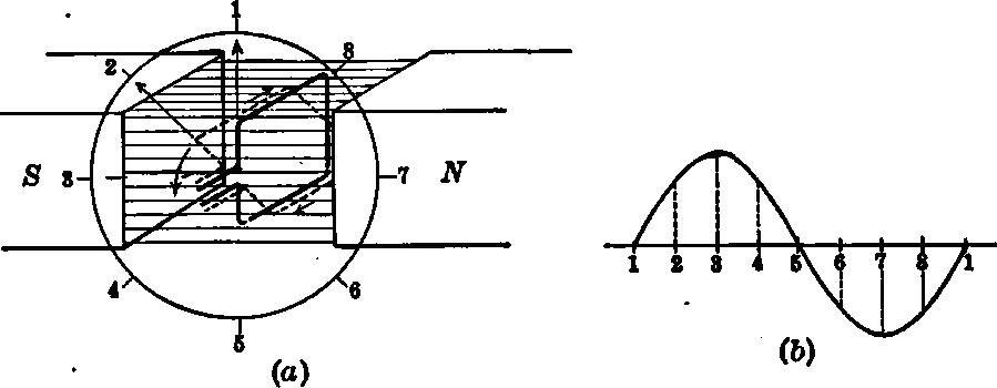
Fig. 6.4. Emf induced in a coil rotating at constant speed in a uniform magnetic field.
at (2) shown in (b). When the coil reaches position (3) the conductors are cutting the lines perpendicularly and are therefore cutting at the maximum possible rate. Hence the electromotive force is a maximum when the coil is in this position. At position (4) the electromotive force is less, due to a lesser rate of cutting. At position (5) no lines are being cut and as in (1) there is no electromotive force. In position (6) the direction of the electromotive force in the conductors will have reversed as each conductor is under a pole of opposite sign to that for positions (1) to (5). The electromotive force increases to a negative maximum at (7) and then decreases until the coil again reaches position (1). After this the coil merely repeats the cycle.
This induced electromotive force is alternating and an emf. varying in the manner shown is called a sine wave of electromotive force. This alternating electromotive force may be impressed on an external circuit by means of two slip-rings as shown below. Each ring is continuous and insulated from the other ring and from the shaft. A spring loaded carbon brush rests on each ring and conducts the current from the coil to the external circuit. If a direct current is desired, that is, one whose direction is always the same, such rings cannot be used. A direct current must always flow into the external circuit in the same direction.
Current taken from rotating coil by means of slip-rings.
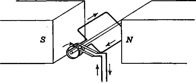
As the coil current, must necessarily be alternating, since the emf. which produces it is alternating, this current must be rectified before it is allowed to enter the external circuit. This rectification can be accomplished by using a split ring such as shown in Fig. 6.5 below. This is split by saw cuts at two points diametrically opposite each other. The two ends of the coil are connected one to each of the sections or segments so produced.
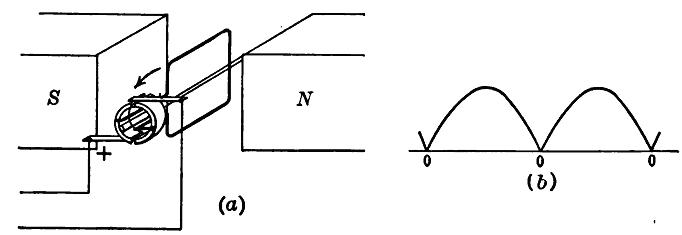
Fig. 6.5. Rectifying effect of a split ring or commutater.
A careful consideration will show that, as the direction of the current in the coil reverses, its connections to the external circuit are simultaneously reversed. Therefore, the direction of flow of the current in the external circuit is not changed. The brushes pass over the cuts in the ring when the coil is perpendicular to the magnetic field or when it is in the so-called neutral plane and is generating no voltage. These neutral points are marked 0-0-0 in figure 6.5 (b). Here it will be seen that the negative half of the wave has been reversed and so made positive.
A voltage with a zero value twice in each cycle, as shown above, could not be used commercially for direct current service. Also a single-coil machine would have a small output for its size and weight. The electromotive force wave may be improved upon by the use of two coils and four commutator segments as shown in the figure 6.6. This gives an open circuit type of winding, since it is impossible to start at any one commutator segment and return to this segment again by following through the entire winding. In this particular arrangement the full electromotive force generated in each coil is not utilized, as one coil passes out of contact with the brushes at points a, a, a in the next figure 6.6 (b), and the voltage shown by the dotted lines is not utilized.
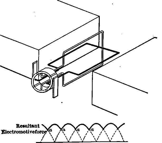
Fig. 6.6 Effect of two coils and four commutator segments upon the electro motive force wave.
Last modified: Tuesday, 1 October 2013, 7:11 AM