Site pages
Current course
Participants
General
MODULE 1. Electro motive force, reluctance, laws o...
MODULE 2. Hysteresis and eddy current losses
MODULE 3. Transformer: principle of working, const...
MODULE 4. EMF equation, phase diagram on load, lea...
MODULE 5. Power and energy efficiency, open circui...
MODULE 6. Operation and performance of DC machine ...
MODULE 7. EMF and torque equations, armature react...
MODULE 8. DC motor characteristics, starting of sh...
MODULE 9. Polyphase systems, generation - three ph...
MODULE 10. Polyphase induction motor: construction...
LESSON 22. Polyphase systems - generation
Reasons for the Use of Polyphase Currents.
In many industrial applications of alternating current, there are objections to the use of single phase power. In a single phase circuit, the power delivered is pulsating. Even when the current and voltage are in phase, the power is zero twice in each cycle. When the power factor is less than unity, the power is not only zero four times in each cycle, but it is also negative twice in each cycle. This means that the circuit returns power to the generator for a part of the time. This is analogous to a single cylinder gasoline engine in which the fly wheel returns energy to the cylinder during the compression part of the cycle. Over the complete cycle, both the single phase circuit and the fly wheel receive an excess of energy over that which they return to the source. The pulsating nature of the power in single phase circuits makes such circuits objectionable in many instances. A polyphase circuit is somewhat like a multi cylinder gasoline engine. With the engine, the power delivered to the fly wheel is practically steady, as one or more cylinders are firing when the others are compressing. This same condition exists in polyphase electrical systems. Although the power of any one phase may be negative at times, the total power is constant if the loads are balanced. This makes polyphase systems highly desirable for power purposes.
The rating of a given motor, or generator, increases with the number of phases, an important consideration. Below are the approximate capacities of a given machine for different numbers of phases, assuming the single phase capacity as 100.
Single phase.................................................................................... 100
Three phase.................................................................................... 148
Direct current.................................................................................. 154
The same machine operating three phase has about 50 per cent, greater capacity than when operating single phase. A minor consideration in favor of three phase power is the fact that with a fixed voltage between conductors, the three phase system requires but three fourths the weight of copper of a single phase system, other conditions such as distance, power loss, etc., being fixed.
Symbolic Notation.
The solutions of problems involving circuits and systems containing a number of currents and voltages are simplified and are less susceptible to error if the current and voltage vectors are designated by some systematic notation, of which the following is one type. If a voltage is acting to send current from point a to point b, in figure 9.1 (a), it shall be
denoted by Eab. On the other hand, if the voltage tends to send current from b to a it shall be denoted by Eba Obviously, Eab = - Eba. It may seem as if alternating currents cannot be considered as having direction since they are undergoing continual reversal in direction. The assumed direction of a current, however, is determined by the actual direction of the flow of energy. In an alternator the energy comes out of the armature and the current is considered as flowing out of the armature, even although it is actually flowing into the armature for half the time.
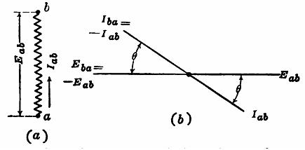
Fig. 9.1 Symbolic Notation
Corresponding to the voltage Eab, in figure 9.1 (a), the current Iab flows from a to b in virtue of this voltage. The current flowing from b to a must be opposite in direction to that flowing from ato b. Therefore Iab = - Iba. This relation is illustrated in figure (b), in which Iab differs in phase from Iba by 180°. Eba is 180° from Eah.
Figure 9.2 represents a circuit network abcde. The parts of the network, ab, bc, etc., may be either resistances, inductances, capacitances, or sources of emfs. It is obvious that the voltage from a to c is equal to the voltage from a to b plus the voltage from b to c. That is, Eac = Eab + Ebc. It is to be noted that when several voltages in series are being considered, the first letter of each subscript must be the same as the last letter of the preceding subscript.
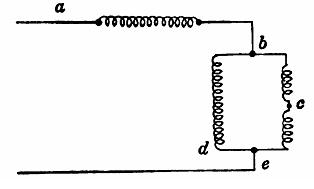
Fig. 9.3 Circuit network.
The figure 9.4 (a) shows vectorially the voltage Eab and the voltage Ecb. To obtain the voltage Eac , Ebc is necessary. Therefore Ecb is reversed giving Ebc. Ebc is now added vectorially to Eab gives Eac.
Currents may be treated in a similar manner, the principle involved being Kirchhof’s first law as shown in figure (b). As may be understood, remember that Kirchoff’s voltage and current laws are applicable here also, except that the quantities are vectorially dealt with since they are AC quantities and have magnitude and direction. Hence these double subscript notations not only distinguishes the various currents and voltages, but the directions in which they act as well. It is to be noted that the use of arrows is not necessary, the subscripts denoting the directions of the vectors.
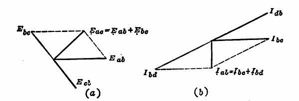
Fig. 9.4 Examples of symbolic notation.
Generation of a three phase voltage.
As three phase is now the most common of the polyphase systems, it will be considered. Figure 9.5 shows three simple coils, 120° apart and fastened rigidly together. These coils are mounted on an axis which can be rotated. The coils are shown rotating in a counter clockwise direction in a uniform magnetic field. The current can be conducted from each of these three coils by means of slip rings, as shown in the figure 9.5 (b). The terminals of coil ‘a’ are connected to rings a', those of b to rings b', etc., making six slip rings in all. Figure 9.6 (a) shows Eoa as the voltage in coil a. Eoa is zero and is increasing in a positive direction when the time t is 0. Obviously the voltage induced in coil b will be 120 electrical time degrees behind Eoa and that induced in coil c will be 240 electrical time degrees behind Eoai as shown in Figs. 9.6 (a) and (b). These three voltages constitute the elementary voltages generated in a three phase system.
An examination of Fig. 9.6 (a) shows that for any particular instant of time, the algebraic sum of these three voltages is zero. When one voltage is zero, the other two are 86.6 per cent, of their maximum values and have opposite signs. When any one voltage wave is at its maximum, each of the others has the opposite sign to this maximum and each is 50 per cent, of its maximum value.
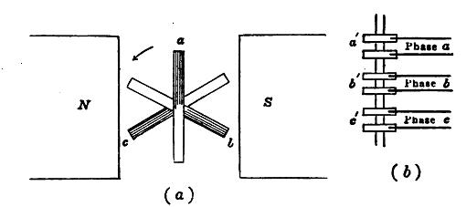
Fig. 9.5 Generation of 3 phase current.
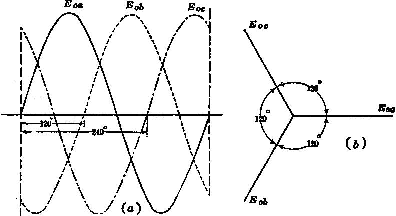
Fig. 9.6. Three phase voltage waves and vector diagram.
Figure 9.6 (b) shows the vectors representing these three voltages, the vectors being 120° apart. Each of the coils of can be connected through its two slip rings to a single phase circuit. This gives six slip rings and three independent single phase circuits. With a rotating field and stationary armature type of generator, which is the most common type in practice, the six slip rings would not be necessary, but six leads would be taken directly from the armature. In practice, however, a machine never supplies three independent circuits by the use of six wires.
Star (Y) connection.
The three coils of Fig. 9.5 are shown in simple diagrammatic form in Fig. 9.7. The three corresponding ends, one for each coil, are tied together at the common point o. This is called the Y connection of the coils. Ordinarily only three wires, aa', bb’ and cc', lead to the external circuit, although the neutral wire oo' is sometimes carried along, making a three phase, four wire system.
Figure 9.8 (a) again shows the three coils and Fig. 9.8 (b) the three corresponding voltage vectors, Eoa, Eob, and Eoc. These three voltages are called the coil or star (Y) voltages. Let it be required to find the three line voltages Eab, Ebc and Eca. The line voltage Eab = Eao + Eob. Eao is not on the original diagram but is obtained by reversing Eoa. Eao is then added vectorially to Eob giving Eab. From geometry, Eab lags the coil voltage Eob by 30° and is 150° behind Eoa. Also, Eab is numerically (magnitude) equal to Ö3 Eob. In a similar manner Ebc = Ebo + Eoc and Eca = Eco + Eoa. These three line voltages are shown in Fig. 9.9.
It is to be noted that in a balanced star (Y) system, the three line voltages are all equal and are 120° apart. Each line voltage is 30° out of phase with one of its respective coil voltages. The three line voltages are each Ö3, or 1.732, times the coil voltage.
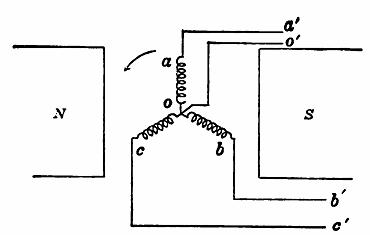
Fig. 9.7 Y (star) connection of generator coils.
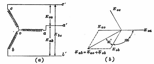
Fig. 9.8 Y connection and corresponding voltage vector diagram.
It is obvious from Fig. 9.8 (a) that the three coil currents Ioa, Iob and Ioc are respectively equal to the three line currents Iaa', Ibb’ and Icc’, as the coil and line is in series.
Therefore, in a star (Y) system the line currents and the respective coil currents are equal. Moreover, as the three coils meet at a common point, the vector sum of the three currents must be zero by Kirchhoff's first law, provided there is no neutral conductor and current. That is
Ioa,+ Iob + Ioc = 0
Power in star (Y) system Figure 9.9 (a) shows the three currents Ioa, Iob and Ioc of coils oa, ob, and oc respectively. Unity power factor is assumed and the three currents are therefore in phase with their respective coil voltages. A balanced system is assumed and the three currents are therefore equal in magnitude.
The coil current Ioa and the line current Iaa' are the same. Therefore, the line current Iaa' is 30° out of phase with the line voltage Eca when the power factor is unity. This is true for each phase.
The power delivered by each coil is
P' = Eoa Ioa (unity power factor; q = 0; cos q = 1)
and the total power delivered by the generator is three times this; P = 3Ecoil Icoil
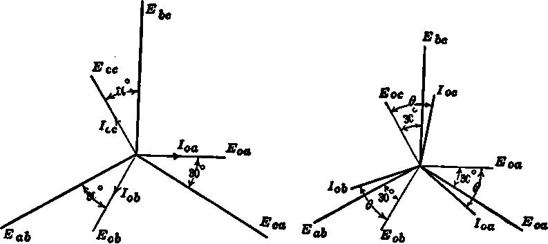
Fig. 9.9 Relation of line to coil voltages and currents in a Y system,
(a) Unity power factor. b. Power factor = cos q.
As the power in the line is the same as that delivered by the generator, substituting Eline/Ö3 for the value of Ecoil ;
P = (3/Ö3) Eline Icoil = Ö3 Eline Iline with the coil current and the line current being equal.
In a balanced three phase system, the line power at unity power factor is equal to Ö3 times the line voltage times the line current.
Figure 9.9 (b) shows this same three phase system when the power factor is no longer unity. Each coil current now lags its respective coil voltage by the angle q.
Each coil power is now
P = 3 Ecoil I coil cos qcoil
The total power is
P = Ö3 Eline Iline cos qcoil
Therefore, in a balanced three phase system, the system power factor is the cosine of the angle between the coil current and the coil voltage.
The angles between the line currents and the line voltages are not power factor angles, for they involve the factors (q — 30°) [Refer Fig. 9.9 (b)] and also (q + 30°), q being the coil power factor angle.
Obviously the system power factor, which is the coil power factor, is
P F. = P / Ö3 Eline Iline
where P is the total system power.
Example.—A three phase alternator has three coils each rated at 1,330 volts and 150 amp. What is the voltage, kva., and current rating of this generator if the three coils are connected in star (Y)?
Eline = Ö3 (1330) = 2,300 volts.
Rating = Ö3 (2300) 150 = 600 kva.
Current rating = 150 amp.
Last modified: Tuesday, 1 October 2013, 7:22 AM