Site pages
Current course
Participants
General
MODULE 1. Electro motive force, reluctance, laws o...
MODULE 2. Hysteresis and eddy current losses
MODULE 3. Transformer: principle of working, const...
MODULE 4. EMF equation, phase diagram on load, lea...
MODULE 5. Power and energy efficiency, open circui...
MODULE 6. Operation and performance of DC machine ...
MODULE 7. EMF and torque equations, armature react...
MODULE 8. DC motor characteristics, starting of sh...
MODULE 9. Polyphase systems, generation - three ph...
MODULE 10. Polyphase induction motor: construction...
LESSON 25. Polyphase induction motor – construction – Equivalent circuit
Slip.
If an armature whose conductors form closed circuits be placed in a rotating field, it will develop torque because of the induced currents, acting in conjunction with the rotating magnetic field. As seen already, the armature can never attain the speed of the rotating field, for if it did, the cutting of conductors by flux would cease, there would be no rotor current and, therefore, no torque. The difference between the speed of the rotating field and that of the rotor is called the revolutions slip of the motor. For example, if the rotor of a four-pole, 50-cycle motor has a speed of 1440 rpm., its revolutions slip is 1500 — 1440 = 60 rpm., where 1500 r.p.m. is its synchronous speed. It is more convenient to express the slip as a fraction of the synchronous speed as
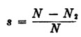 where N2 is actual rotor speed
The slip of the above motor would be (1500-1440)/1500 = 0.04 = 4%. The full-load slip in commercial motors varies from 1 to 10 per cent., depending upon the size and the type of motor.
Rotor Frequency and Induced Emf.
If the rotor of a two-pole, 50 cycle motor is at standstill and voltage is applied to the stator, each rotor conductor will be cut by a north pole 50 times per second and by a south pole 50 times per second, as this is the speed of the rotating field. If the stator be wound for four poles, the speed of the rotating field is halved, but each conductor is then cut by two north and two south poles per revolution of the field and therefore by 50 north and 50 south poles per second, the same as in the two-pole motor. Consequently, the frequency of the rotor currents at standstill will be the same as the stator frequency. This holds true for any number of poles. At standstill the motor is a simple static transformer, the stator being the primary and the rotor being the secondary. If the rotor of the above 50 cycle motor revolves at half speed in the direction of the rotating field (s = 0.5), the rotor conductors are cut by just one-half as many north and south poles per second as when standing still and the frequency of the rotor currents is therefore 25 cycles per second. Generalizing, f2 = sf, where f2 is the rotor frequency, s the slip, and f the stator frequency.
Example. What is the frequency of the rotor current of a 50 cycle, six-pole induction motor, if the rotor speed is 900 rpm.
The synchronous speed = 1000
Rotor current frequency = 50 × (1000-900)/1000 = 5 hz
Squirrel Cage Motors
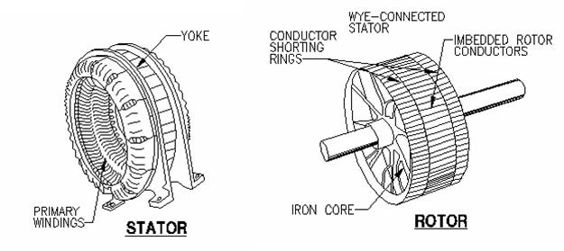
Fig. 10.5 Construction of a squirrel cage motor
A squirrel-cage motor consists essentially of two units, namely Rotor and Stator. The rotor (or secondary) is also constructed of steel laminations, but the windings consist of conductor bars placed approximately parallel to the shaft and close to the rotor surface. These windings are connected at each end of the rotor, by a solid ring. The rotors of large motors have bars and rings of copper connected at each end by a conducting end ring made of copper or brass. The joints between the bars and end rings are usually electrically welded into one unit, with blowers mounted on each end of the rotor. In small squirrel-cage rotors, the bars, end rings, and blowers are of aluminum cast in one piece instead of welded together.
The stator (or primary) consists of a laminated sheet-steel core with slots where the insulated coils are placed. The coils are grouped and connected to form a definite polar area and to produce a rotating magnetic field when connected to a polyphase alternating current. The air gap between the rotor and stator must be very small in order for the best power factor to be obtained. The shaft must, therefore, be very rigid and furnished with quality bearings of the sleeve or ball-bearing type. In a squirrel-cage motor, the secondary winding takes the place of the field winding in a synchronous motor. As in a synchronous motor, the currents in the stator set up a rotating magnetic field. This field is produced by the increasing and decreasing currents in the windings. When the current increases in the first phase, only the first winding produces a magnetic field. As the current decreases in this winding and increases in the second, the magnetic field shifts slightly, until it is all produced by the second winding. When the third winding has maximum current flowing in it, the field is shifted a little more. The windings are so distributed that this shifting is uniform and continuous. It is this action that produces a rotating magnetic field. As this field rotates, it cuts the squirrel-cage conductors, and voltages are set up in these just as though the conductors were cutting the field in a DC generator. These voltages cause currents to flow in the squirrel-cage circuit – through the bars under the adjacent south poles into the other end ring, and back to the original bars under the north poles to complete the circuit. The current flowing in the squirrel-cage, down one group of bars and back in the adjacent group, makes a loop that establishes magnetic fields in the rotor core with north and south poles. This loop consists of one turn, but there are several conductors in parallel and the currents may be large. The poles in the rotor are attracted by the poles of the rotating field set up by the currents in the armature winding and follow them around in a manner similar to the way in which the field poles follow the armature poles in a synchronous motor.
EQUIVALENT CIRCUIT
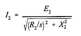
At standstill (slip, s = 1), the rotating magnetic field produced by the stator has the same speed with respect to the rotor windings as with respect to the stator windings. Thus, the frequency of the rotor currents, f2, is the same as the frequency of the stator currents f. At synchronous speed (s = 0), there is no relative motion between the rotating field and the rotor, and the frequency of rotor current is zero. At intermediate speeds the rotor current frequency is proportional to the slip, as already seen earlier. Noting that the rotor currents are of slip frequency, we have the rotor equivalent circuit (on a per-phase basis) in figure below (a), which gives the rotor current, I2, as
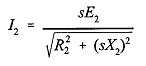
Here, E2 is the induced rotor emf at standstill; X2 is the rotor leakage reactance per phase at standstill; and R2 is the rotor resistance per phase. This may also be written as
So we can redraw the circuit in figure Fig 10.6 (a) as figure (b).
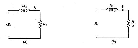
Fig. 10.6 Equivalent circuit of rotor
In order to include the stator circuit, the induction motor may be viewed as a transformer with an air gap, having a variable resistance in the secondary. Thus the primary of the transformer corresponds to the stator of the induction motor, whereas the secondary corresponds to the rotor on a per-phase basis. Because of the air gap, however, the value of the magnetizing reactance, X, tends to be low as compared to that of a true transformer. As in a transformer, we have a mutual flux linking both the stator and rotor, represented by the magnetizing reactance and various leakage fluxes. For instance, the total rotor leakage flux is denoted by X2. Considering the rotor as being coupled to the stator as the secondary of a transformer is coupled to its primary, we may draw the circuit as shown in Fig 10.7. To develop this circuit further, we need to express the rotor quantities as referred to the stator. For this purpose we must know the transformation ratio, as in a transformer.
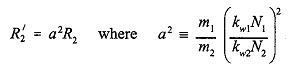
The voltage transformation ratio in the induction motor must include the effect of the stator and rotor winding distributions. It can be shown that, for a cage-type rotor, the rotor resistance per phase, R'2 referred to the stator, is
Here kw1 = winding factor of the stator having N1, series-connected turns per phase
kw2 = winding factor of the rotor having N2 =/4 series-connected turns per phase, for a cage rotor,
where p is the number of poles
ml = number of phase on the stator
m2 = number of bars per pole pair
R2 = resistance of one bar
Similarly,
X2’ = a2X2
where X2’ is the rotor leakage reactance per phase, referred to the stator.
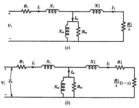
Fig. 10.7 Equivalent circuit of motor
Bearing in mind both the similarities and the differences between an induction motor and a transformer, we now refer the rotor quantities to the stator to obtain the exact equivalent circuit (per phase) shown above in figure (a). For reasons that will become immediately clear,
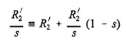
we split R2’ / s as to obtain the circuit shown in figure (b) above. Here, R'2 is simply the per-phase standstill rotor resistance referred to the stator and R'2 (1- s)/s is a per-phase dynamic resistance that depends on the rotor speed and corresponds to the load on the motor.
Last modified: Tuesday, 1 October 2013, 9:13 AM