Site pages
Current course
Participants
General
MODULE 1. Overview of renewable energy sources
MODULE 2. Characterization of Biomass
MODULE 3. Thermochemical conversion Technology (TCCT)
MODULE 4. Biochemical conversion Technology-Biogas...
MODULE 5. Bio-fuels (BCCT)
MODULE 6. Solar Energy Conversion System (SECS)
MODULE 7. Hydro-Energy Conversion System (HECS)
MODULE 8. Wind Energy Conversion System (WECS)
MODULE 9. Ocean Energy Conversion System (OECS)
MODULE 10. Energy conservation in agriculture
LESSON 7. Gasifier Technology
Gasification
The process to convert biomass solid raw material into fuel gas or chemical feedstock gas (syngas) is called gasification or thermochemical gasification.
Gasification agent
In order to convert solid biomass into inflammable gas, a substance to promote the chemical reaction is necessary. This substance is called the gasification agent, and mainly air (N2, O2), oxygen (O2), H2O, or CO2 are applied as an appropriate mixture. Air (only O2 reacts) and O2heat by oxidation, and increased O2 decreases the effective amount of inflammable gas.
Fundamental phenomenon of biomass gasification
Fundamental gasification processes are as follows:
(a) Evaporation of surface moisture
Surface moisture evaporates from the raw material at the water boiling point (depends on pressure). Inner moisture remains when the raw material is large.
(b) Evaporation of inherent moisture
Following surface moisture evaporation, inherent moisture evaporates at 110-120°C.
(c) Volatilization
Thermal decomposition of biomass begins at 200-300°C, and CO, CO2, H2 and H2O are vaporized as gas. Thermal decomposition is a heat generating reaction which is a characteristicphenomenon of biomass CnHmOp).
(d) Volatilization and gasification reaction
The temperature is raised further during volatilization, and the volatile matter of the lightweight hydrocarbons (CxHy: where x and y are integers of at least 1; a low value of x indicates lightness and a high value of x indicates heaviness) is transformed into heavy CxHy with a high boiling point. Subsequently, the CxHy reacts with the gasifying agent for conversion to lightweight molecule clean gas, although tar and soot can form when diffusion of the gasifying agent is slow and the CxHy condenses.
(e) Char gasification
Following volatilization of the volatile content in the raw material biomass, the fixed carbon and ash become char, and the char is heated to the surrounding temperature. The subsequent reaction with the gasifying agent transforms the carbon into CO and CO2. However, in cases where the gasifying agent contains excess steam and the surrounding temperature is over 750°C, a wet gas reaction occurs (C+H2O ( CO+H2) producing gas composed mainly of CO, CO2 and H2.
(f) Char residue
The reaction rate of the wet gas reaction is slow, and char residue can easily form. The formationof tar, soot and char tends to reduce efficiency, as well causing equipment trouble.
Characteristics of gasification product gas
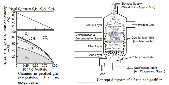
Gasification generally adopts the direct gasification method with partial combustion of raw material to raise the temperature. Raw materials are mainly wood chips and corn stalks. Most gasification furnaces use normal pressure and a direct gasification process. To keep the reaction temperature at 800°C and above for direct gasification, air, oxygen and steam (as appropriate) are required for the gasification agent. For this purpose, approximately 1/3 of the oxygen required for complete combustion (known as the oxygen ratio) is supplied, with partial combustion (partial oxidation) causing gasification. The calorific value of product gas depends on the percentage of inflammable gas (CO, H2, CxHy) contained. Generally, gas can be divided into low calorie gas (4-12 MJ/m3), medium calorie gas (12-28 MJ/m3) and high calorie gas (above 28 MJ/m3). For the most part, direct gasification of biomass yields low calorie gas. Fig. 4.2.1 presents composition of the product gas from rice straw when steam and oxygen is employed as gasifying agent. The ratio between the calorific content of the biomass and that of the product gas (at room temperature) is called cold gas efficiency.
Gasification equipment and a practical example
Here is shown a fixed bed gasifier, based on the combustion or gasification of solid fuel, and featuring a comparatively simple structure and low equipment cost. Fig. 4.2.2 shows a concept diagram of the gasifier. Wood chips of about 2.5-5 cm are generally used as the raw material. They are supplied from the upper feed port, and layered in the furnace. The gasifying agent (air, oxygen, steam or a mixture thereof) is supplied from the bottom in a rising flow (some systemsuse a descending flow). The gasification reaction proceeds from the bottom towards the top. From the bottom upward, individual layers are formed due to the changes accompanying gasification of the raw material, in the order of ash, char, volatilized and decomposed material, and product. The product gas is obtained at the top.
Principles of solid fuel gasification
All internal combustion engines actually run on vapor, not liquid. The liquid fuels used by gasoline engines are vaporized before they enter the combustion chamber above the pistons. In diesel engines, the fuel is sprayed into the combustion chamber as fine droplets which burn as they vaporize.
The purpose of a Gasifier, then, is to transform solid fuels into gaseous ones and to keep the gas free of harmful constituents. A gas generator unit is simultaneously an energy converter and a filter. In these twin tasks lie its advantages and its difficulties. In a sense, gasification is a form of incomplete combustion-heat from the burning solid fuel creates gases which are unable to burn completely because of the insufficient amounts of oxygen from the available supply of air. The same chemical laws, which govern combustion processes, also apply to gasification. There are many solid biomass fuels suitable for gasification - from wood and paper to peat, lignite, and coal, including coke derived from coal. All of these solid fuels are composed primarily of carbon with varying amounts of hydrogen, oxygen, and impurities, such as sulfur, ash, and moisture. Thus, the aim of gasification is the almost complete transformation of these constituents into gaseous form so that only the ashes and inert materials remain. In creating wood gas for fueling internal combustion engines, it is important that the gas not only be properly produced, but also preserved and not consumed until it is introduced into the engine where it may be appropriately burned.
Gasification is a physicochemical process in which chemical transformations occur along with the conversion of energy. The chemical reactions and thermochemical conversions which occur inside a wood gas generator are too long and too complicated to be covered here; however, such knowledge is not necessary for constructing and operating a wood Gasifier. By weight, gas (wood gas) produced in a Gasifier unit contains approximately 20% hydrogen (H2), 20% carbon monoxide (CO), and small amounts of methane, all of which are combustible, plus 50 to 60% nitrogen (N2). The nitrogen is not combustible; however, it does occupy volume and dilutes the wood gas as it enters and burns in an engine. As the wood gas burns, the products of combustion are carbon dioxide (CO2) and water vapor (H20).
One of the by-products of wood gasification is carbon monoxide, a poisonous gas. The toxic hazards associated with breathing this gas should be avoided during refueling operations or prolonged idling, particularly in inadequately ventilated areas. Except for the obvious fire hazard resulting from the combustion processes inside the unit, carbon monoxide poisoning is the major potential hazard during normal operation of these simplified Gasifier units.
The Stratified Downdraft Gasifier
Until the early 1980s, wood gasifiers all over the world (including the World War II designs) operated on the principle that both the fuel hopper and the combustion unit be absolutely airtight; the hopper was sealed with a top or lid which had to be opened every time wood was added. Smoke and gas vented into the atmosphere while wood was being loaded; the operator had to be careful not to breathe the unpleasant smoke and toxic fumes. Over the last few years, a new Gasifier design has been developed through cooperative efforts among researchers at the Solar Energy Research Institute in Colorado, the University of California in Davis, the Open University in London, the Buck Rogers Company in Kansas, and the Biomass Energy Foundation, Inc., in Florida. This simplified design employs a balanced, negative-pressure concept in which the old type of sealed fuel hopper is no longer necessary. A closure is only used to preserve the fuel when the engine is stopped. This new technology has several popular names, including "stratified, downdraft gasification" and "open top gasification."
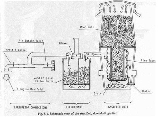
Several years of laboratory and field-testing have indicated that such simple, inexpensive gasifiers can be built from existing hardware and will perform very well as emergency units. A schematic diagram of the stratified, downdraft Gasifier is shown in Fig. S-1.During operation of this Gasifier, air passes uniformly downward through four zones, hence the name stratified: The uppermost zone contains unreacted fuel through which air and oxygen enter. This region serves the same function as the fuel hopper in the older, World War II designs. In the second zone, the wood fuel reacts with oxygen during pyrolysis. Most of the volatile components of the fuel are burned in this zone and provide heat for continued pyrolysis reactions. At the bottom of this zone, all of the available oxygen from the air should be completely reacted. The open top design ensures uniform access of air to the pyrolysis region. The third zone is made up of charcoal from the second zone. Hot combustion gases from the pyrolysis region react with the charcoal to convert the carbon dioxide and water vapor into carbon monoxide and hydrogen. The inert char and ash, which constitute the fourth zone, are normally too cool to cause further reactions; however, because the fourth zone is available to absorb heat or oxygen as conditions change, it serves both as a buffer and as a charcoal storage region. Below this zone is the grate. The presence of char and ash serves to protect the grate from excessive temperatures.
The stratified, downdraft design has a number of advantages over the World War II gasifier designs. The open top permits fuel to be fed more easily and allows easy access. The cylindrical shape is easy to fabricate and permits continuous flow of fuel. No special fuel shape or pretreatment is necessary; any blocky fuel can be used. The foremost question about the operation of the stratified, downdraft gasifier concerns char and ash removal. As the charcoal reacts with the combustion gases, it eventually reaches a very low density and breaks up into a dust containing all of the ash as well as a percentage of the original carbon. This dust may be partially carried away by the gas and might eventually begin to plug the gasifier.
Hence, it must be removed by shaking or agitation. When the stratified gasifier unit is used to power vehicles, it is automatically shaken by the vehicle's motion. An important issue in the design of the stratified, downdraft gasifier is the prevention of fuel bridging and channeling. High-grade biomass fuels, such as wood blocks or chips, will flow down through the gasifierbecause of gravity and downdraft air flow. However, other fuels (such as shredded chips, sawdust, and bark) can form a bridge, which will obstruct continuous flow and cause very high temperatures. Bridging can be prevented by stirring, shaking, or by agitating the grate or by having it agitated by the vehicle's movement. For prolonged idling, a hand-operated shaker has been included in the design in this report.
A prototype unit of the stratified, downdraft gasifier design (see Figs. S-2 and S-3) has been fabricated according to the instructions in this report; however, it has not been widely tested at this time. The reader is urged to use his ingenuity and initiative in the construction of his own wood gas generator. As long as the principle of air tightness in the combustion regions, in the connecting piping, and in the filter units is followed, the form, shape, and method of assembly is not important. The wood gasifier design presented in this report has as its origin the proven technology used in World War II during actual shortages of gasoline and diesel fuel. It should be acknowledged that there are alternate technologies (such as methane production or use of alcohol fuels) for keeping internal combustion engines in operation during a prolonged petroleum crisis. The wood gasifier unit described in this report represents only one solution to the problem.
Imbert' Gasifier
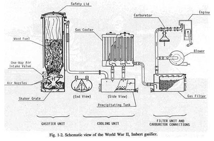
The constricted hearth, downdraft Gasifier is sometimes called the 'Imbert' Gasifier after its inventor, Jacques Imbert; although, it has been commercially manufactured under various names. Such units were mass-produced during World War II by many European automotive companies, including General Motors, Ford, and Mercedes-Benz. These units cost about $1500 (1985 evaluation) each. However, after World War II began in 1939, it took six to eight months before factory-made gasifiers were generally available. Thousands of Europeans were saved from certain starvation by home-built, simple Gasifier units made from washing machine tubs, old water heaters, and metal gas or oxygen cylinders. Surprisingly, the operation of these units was nearly as efficient as the factory-made units; however, the homemade units lasted for only about 20000 miles with many repairs, while the factory-made units operated, with few repairs, up to 100,000 miles. In Fig. 1-2 the upper cylindrical portion of the Gasifier unit is simply a storage bin or hopper for wood chips or other biomass fuel. During operation, this chamber is filled every few hours as needed. The spring-loaded, airtight cover must be opened to refill the fuel hopper; it must remain closed and sealed during Gasifier operation. The spring permits the cover to function as a safety valve because it will pop open in case of any excessive internal gas pressure. About one-third of the way up from the bottom of the Gasifier unit, there is a set of radially directed air nozzles; these allow air to be injected into the wood as it moves downward to be gasified. In a gas generator for vehicle use, the down stroke of the engine's pistons creates the suction force which moves the air into and through the Gasifier unit; during startup of the Gasifier a blower is used to create the proper airflow. The gas is introduced into the engine and consumed a few seconds after it is made. This gasification method is called "producer gas generation," because no storage system is used; only that amount of gas demanded by the engine is produced. When the, engine is shut off, the production of gas stops. During normal operation, the incoming air burns and pyrolyzes some of the wood, most of the tars and oils, and some of the charcoal that fills the constricted area below the nozzles.
Most of the fuel mass is converted to gas within this combustion zone. The ImbertGasifier is, in many ways, self-adjusting. If there is insufficient charcoal at the air nozzles, more wood is burned and pyrolyzed to make more charcoal. If too much charcoal forms, then the charcoal level rises above the nozzles, and the incoming air burns the charcoal. Thus, the combustion zone is maintained very close to the nozzles. Below this combustion zone, the resulting hot combustion gases - carbon dioxide (CO2) and water vapor (H2O) - pass into the hot charcoal where they are chemically reduced to combustible fuel gases: carbon monoxide (CO) and hydrogen (H2). The hearth constriction causes all gases to pass through the reaction zone, thus giving maximum mixing and minimum heat loss. The highest temperatures are reached in this region. Fine char and ash dust can eventually clog the charcoal bed and will reduce the gas flow unless the dust is removed. The charcoal is supported by a movable grate which can be shaken at intervals. Ash buildup below the grate can be removed during cleaning operations. Usually, wood contains less than 1% ash (by weight). However, as the charcoal is consumed, it eventually collapses to form a powdery charcoal/ash mixture which may represent 2 to 10% (by weight) of the total fuel mass.
The cooling unit required for the lmbertGasifier consists of a water filled precipitating tank and an automotive radiator type gas cooler. The precipitating tank removes all unacceptable tars and most of the fine ash from the gas flow, while the radiator further cools the gas. A second filter unit, containing a fine mesh filtration material, is used to remove the last traces of any ash or dust that may have survived passage through the cooling unit. Once out of the filter unit, the wood gas is mixed with air in the vehicle's carburetor and is then introduced directly into the engine's intake manifold. The World War II, ImbertGasifier requires wood with alow moisture content (less than 20% by weight) and a uniform, blocky fuel in order to allow easy gravity feed through the constricted hearth. Twigs, sticks, and bark shreds cannot be used. The constriction at the hearth and the protruding air nozzles present obstructions to the passage of the fuel and may created ridging and channeling followed by poor quality gas output, as unpyrolyzed fuel falls into the reaction zone.
SUGARCANE LEAF-BAGASSE GASIFIERS
Certain critical engineering design norms of the gasification system were first developed on a laboratory-scale model and were then validated on a bench-scale model 6, 7 . These norms were then used to design a full-fledged commercial scale system with a thermal output of 1080 MJ h-1 . This system (presently installed in the NARI campus) is seen in Fig. 1. It comprises of a reactor, a gas conditioning system, a biomass feeding system and the instrumentation and controls. A schematic diagram of this system is shown in Fig. 2. The salient features of these components are given below.
Reactor : This was a downdraft, throatless and open-top reactor with an internal diameter of 75 cm and an active bed height of 1.25 m. It was designed for a heavy-duty cycle of 7500 hour per year operation. High temperature resisting firebricks conforming to IS 8 grade were used for the hot face followed by a cold face insulation.
Gas conditioning system : A completely dry dust collection system eliminated altogether the problem of wastewater. This consisted of a high temperature char/ash coarse settler and a high efficiency cyclone separator. A specifically designed high temperature resisting induced-draft fanensured that the entire system is under negative pressure so that in the event of leaks, outside air got sucked into the system, but the combustible gas did not leak out. Thus, this design is very environment-friendly. The char-ash from the coarse settler and the cyclone was collected in barrels and emptied in an ash pit once every forty-five minutes. This char-ash which typically has a gross calorific value of 18.9 MJ kg-1 can be briquetted to form an excellent fuel, or can be used as a soil conditioner 8, 9 .
Biomass feeding system : This consisted of a scraper drag-out conveyor and a hopper to convey the biomass fuel from the storage pile to the reactor. The conveyor was completely enclosed.
Instrumentation and Control System :A Programmable Logic Controller (PLC)-based control system seen in Fig. 3 was designed to take automatic corrective actions under certain critical conditions. Thus, the biomass feeding and ash removal rates were fully controlled by this system. Besides, it also helped the operator in trouble-shooting by monitoring temperatures at various critical points in the gasification system. Automatic burner sequence controllers were provided for ignition of the producer gas.
The gasification system was extremely simple to operate. A cold start took about ten-fifteen minutes whereas a hot start was affected in less than five minutes. Only two operators per shift of eight hours were required to operate the system, including the fuel and ash handling operations.
Last modified: Tuesday, 1 October 2013, 11:05 AM