Site pages
Current course
Participants
General
MODULE 1. Overview of renewable energy sources
MODULE 2. Characterization of Biomass
MODULE 3. Thermochemical conversion Technology (TCCT)
MODULE 4. Biochemical conversion Technology-Biogas...
MODULE 5. Bio-fuels (BCCT)
MODULE 6. Solar Energy Conversion System (SECS)
MODULE 7. Hydro-Energy Conversion System (HECS)
MODULE 8. Wind Energy Conversion System (WECS)
MODULE 9. Ocean Energy Conversion System (OECS)
MODULE 10. Energy conservation in agriculture
LESSON 30. Ocean Energy conversion systems
Oceans cover most of the (70%) of the earth’s surface and they generatethermal energy from the sun and produce mechanical energy from the tidesand waves.The solar energy that is stored in the upper layers of the tropical ocean, ifharnessed can provide electricity in large enough quantities to make it aviable energy source.World ocean temperaturediffers at a depth of1000 m. This energy source isavailable throughout theequatorial zone around theworld or about 20 degreesnorth and south of theequator where most ofthe world's population lives.
Tides
The ocean tides are caused by the gravitational forces from the moon and the sun and the centrifugal forces on the rotating earth. These forces tend to raise the sea level both on the side of the earth facing the moon and on the opposite side. The result is a cyclic variation between flood (high) and ebb (low) tides with a period of 12 hours and 25 minutes or half a lunar day. Additionally, there are other cyclic variations caused by the combined effect of the moon and the sun. The most important ones are the 14 days spring tide period between high flood tides and the half year period between extreme annual spring tides. Low flood tides follow similar cycles. The ocean bottom topography has pronounced effect on the local tides. The tides are accurately predictable.
The world potential for tidal power exceeds 450 TWh In the open ocean, the maximum amplitude of the tides is about one meter. Tidal amplitudes are increased substantially towards the coast, particularly in estuaries. This is mainly caused by shelving of the sea bed and funneling of the water by estuaries. In some cases the tidal range can be further amplified by reflection of the tidal wave by the coastline or resonance. This is a special effect that occurs in long, trumpet-shaped estuaries, when the length of the estuary is close to one quarter of the tidal wave length. These effects combine to give a mean spring tidal range of over 11 m in the Severn Estuary (UK). Tidal energy is highly predictable
in both amount and timing. The available energy is approximately proportional to the square of the tidal range. Extraction of energy from the tides is considered to be practical only at those sites where the energy is concentrated in the form of large tides and the geography provides suitable sites for tidal plant construction. Such sites are not commonplace but a considerable number have been identified in the UK, France, eastern Canada, the Pacific coast of Russia, Korea, China, Mexico and Chile. Other sites have been identified along the Patagonian coast of Argentina, Western Australia and western India.
Types of tidal energy:
The potential energy of sea level differences associated with the tidesDams close off sea basins at flood or high tide and low head turbines throughwhich the trapped water are released at low tide.
The kinetic energy of the tidal currentsWater mills submerged in the tidal stream - tidal stream turbines. The fluid power of the flow is given by:
P=1/2 ρV3A W/m2,
ρ=1025 kg/m3
A=Area swept by turbine
P=velocity of current
Consider a rectangular basin with a constant surface area of A,
Tidal range: R,
Total volume of basin water = AR,
Mass = ρAR,
Potential energy available = ρArg (R/2),
Tidal Period = T,
Average potential energy extracted = ρAR2g/2T,
The center of gravity for the mass of water will be at R/2 above the lower tide level.
Wave Energy
Waves, particularly those of large amplitude, contain large amounts of energy. Wave energy is in effect a stored and concentrated form of solar energy, since the winds that produce waves are caused by pressure differences in the atmosphere arising from solar heating. The strong winds blowing across the oceans create large waves, making many coastal regions around the globe ideally suited to wave energy schemes. The global wave power resource is estimated to be about 2 TW with electricity generation potential of about 2000 TWh annually. Air flowing over the sea exerts a tangential stress on the water surface resulting in the formation and growth of waves Turbulent air flow close to the water surface creates rapidly varying shear stresses causing ripples, known as capillary waves. Capillary waves create more water surface increasing the friction between water and wind. This adds more energy, which increases the size of the waves, making them larger and larger. When the winds slow down or stop, the waves continue their journey, gradually but very slowly losing their energy. Waves may travel thousands of km before rolling ashore. This predictability of waves is one of the advantages of wave energy as an energy source. An ocean wave in deep water appears to be a massive moving object - a crest of water travelling across the sea surface. An ocean wave is the movement of energy. Out in the ocean where waves move the water's surface up and down, the water is not moving towards the shore. So, an ocean wave does not represent a flow of water. Instead it represents a flow of motion or energy from its origin to its eventual break up. This break up may occur in the middle of the ocean or against the coast.
The water molecules in an ocean wave move in circles. The behavior of waves depends largely on the relationship between a wave's size and the depth of water through which it is moving. The movement of water molecule changes from circular to ellipsoidal as a wave approaches the coast and water depths decrease. Eventually when the wave rolls up on a beach - and when most of us observe waves - the movement is mostly horizontal. When talking of ocean wave, and a potential deployment of Wave Dragon, the influence of water depth is negligible. Ocean waves are as mentioned above essential movement of energy. Waves consist of two kinds of energy. The individual water molecules are moving steadily and rather slowly in a circular way, and this energy – kinetic energy - can be utilized in different kinds of wave energy converters, either directly via some kind of propeller or indirectly by Oscillating Water Columns wave energy converters In its circular movement the individual water molecules are elevated above the still-water line and thus represent a potential energy.
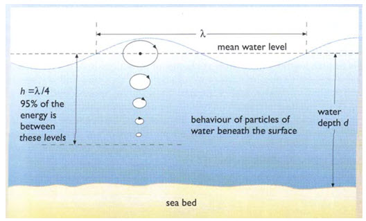
Fig. Distribution of Ocean Surface Wave Energy
Wave PowerP= (ρg2H2T)/32π W/m;
where,
T= wave period
Wave energy represents a concentrated form of energy like solar energy. Solar power of 100W/m2 corresponds to over 1000kW/m2 of wave crest length. The power of waves depends on the wind; the most regular wind, and thus the most workable wave power, is generated between 30 and 60 degree of latitude. The largest potential is located in deep water.
Types of wave energy technology
Many systems have been developed. Some have stayed at the R&D stage while otherswork on the shoreline. Several ways to harness energy from waves have been developedand are described below.
1. Oscillating Water Column (OWC)
This device is based on the pressure of the enclosed air in a cavity (column of air). Thepressure of air varies as a function of the level of water in this cavity. The higher the levelof water, the greater the air pressure. The air located in the chamber is drained off
through a generator (Wells turbine). The advantage is that OWC can be used in both directions, ascent and descent of wave. However, the Wells turbine needs energy to getstarted. One represents 500kW.
2. The Pelamis
The Pelamis system looks like a ‘sea snake.’ It is a succession of floated empty segmentsin 50m or more water depth. The segments are linked to each others by hinged joints. Theenergy is produced when a wave runs on the length of the systems. Joints, connected topump oil and to a hydraulic generator (smoothing systems), allow movement betweeneach section and produce electricity as the wave moves by.
Main features about the Pelamis:
Overall length = 390x220m
Diameter = 14000 m3
Overall power rating = 0.75MW
Nominal wave power = 55kW/m
Annual power production = 2.7GWh
Water depth = >50m
3. The Wave Dragon
The wave dragon is a system that temporarily stores water in a reservoir before fallinginto a turbine; in this way it is transformed into electricity. The waves reach the reservoirby way of a ramp. After going through an alternator, the water is released to the source.This means of generation can be comparable to a dam with three steps: absorption,storage and power take off.The design is very complex (requiring optimization of overtopping, adapting of mooringsystem, reducing the effect of wave force…). It utilizes the potential of waves directlyand does not use the motion. On the other hand, this system has several advantages,especially its sturdiness. Like the Pelamis, this device does not need the shore and can beset up in ocean zones with high potential waves (with no losses of energy because of thecoastal area), and even in extreme environments.The Wave Dragon unit produces electricity corresponding to the average annual wavepower map to:
in a 24kW/m wave climate = 12 GWh/year
in a 36kW/m wave climate = 20 GWh/year
in a 48kW/m wave climate = 35 GWh/year
in a 60kW/m wave climate = 43 GWh/year
in a 72kW/m wave climate = 52 GWh/year
Main features about the largest Wave Dragon:
Width and length = 390x220m
Reservoir = 14,000 m3
Rated power/unit = 11MW
Annual power production/unit = 35GWh
Water depth = >30m
4. The Archimedes Wave Swing (AWS)
The Archimedes Wave Swing wave energy converter is a cylindrical buoy which is moored on the seabed. The working procedure is based on the principle of the float (Archimedes). The only moving part is an air-filled floater. Waves create an ‘up and down’ movement due to applied pressure on the floater which is located in a lower fixed cylinder. The buoyancy is ensured by the pressure and depression applied on the air-filled chamber. Thanks to a linear generator based in the cylinder, this movement is converted into electricity and then transmitted to the shore. Furthermore, the following characteristics are required for optimal use:
-
Location exposed to ocean swells - e.g. western coast of British Isles, Ireland,
-
France, Spain or Portugal
-
40 - 100m of water depth outside of main commercial shipping lanes
-
Secure electricity power grid onshore
-
Industrial port within 12 hours sailing time
-
Sea-bed suitable for laying power cables to shore
Each unit is currently rated at 1.2 Megawatts, equal to the electrical demand ofapproximately 500 households’ energy. The first AWS machine was installed off Orkneyin 2007 by AWS Ocean Energy with eventual plans to create a 100-machine wave park ata cost of £250 million.
5. The McCabe Wave Pump
The McCabe Wave Pump has three pontoons linearly hinged together and pointedparallel to the wave direction. The center pontoon is attached to a submerged damperplate, which causes it to remain still relative to fore and aft pontoons. Hydraulic pumpsattached between the center and end pontoons are activated as the waves force the endpontoons up and down. The pressurized hydraulic fluid can be used to drive a motorgenerator (rated at 250–500 kW) or to pressurize water for desalinization. A full-size 40mprototype was tested off the coast of Ireland in 1996, and commercial devices are beingoffered by the manufacturer.
6. The Power Buoy
The device is a prototype system including a submerged buoy (1m below the level ofwater). Inside the buoy, a piston follows the movement of the waves’ rise and fall tooutput energy from the internal generator (immobile part). Then electricity is sent toshore by an underwater cable as is the case with all previous devices.
7. The AquaBuOY
The AquaBuOY™ Wave Energy Conversion is being developed by the AquaEnergy Group, Ltd. It is a point absorber that is the third generation of two Swedish designs that utilize wave energy to pressurize a fluid that is then used to drive a turbine generator. The vertical movement of the buoy drives a broad, neutrally buoyant disk acting as a water piston contained in a long tube beneath the buoy. The water piston motion in turn elongates and relaxes a hose containing seawater, and the change in hose volume acts as a pump to pressurize the seawater. The AquaBuOY design has been tested using a full-scale prototype, and a 1-MW pilot offshore demonstration power plant is being developed offshore at Makah Bay, Washington. The Makah Bay demonstration will include four units rated at 250 kW
placed 5.9 km (3.2 nautical miles) offshore in water approximately 46 meters deep.
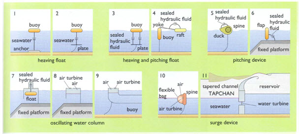
Fig. Wave Energy Conversion Types
Wave Energy Devices
Shoreline devices
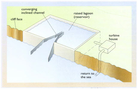
1.The convergent channel (TAPCHAN)
The Tapchan comprises a gradually narrowing channel with wall heights typically 3 to 5 m above mean water level. The waves enter the wide end of the channel and, as they propagate down the narrowing channel, the wave height is amplified until the wave crests spill over the walls to a reservoir which provides a stable water supply to a conventional low head turbine. The requirements of low tidal range and suitable shoreline limit the use of this device.
2.Oscillating water column device (OWC)
The OWC comprises a partly submerged concrete or steel structure, which has an opening to the sea below the water line, thereby enclosing a column of air above a column of water. As waves impinge on the device, they cause the water column to rise and fall, which alternately compresses and depressurizes the air column. This air is allowed to flow to and from the atmosphere through a turbine which drives an electric generator. Both conventional (i.e. unidirectional) and self- rectifying air turbines have been proposed. The axial-flow Wells turbine, invented in the 1970s, is the best known turbine for this kind of application and has the advantage of not requiring rectifying air valves.
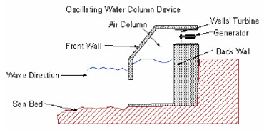
Fig. Oscillating water column device.
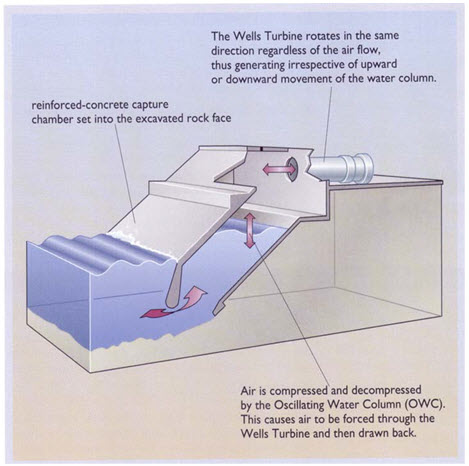
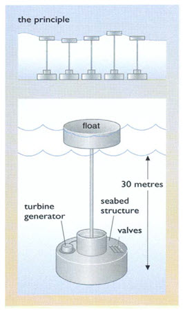
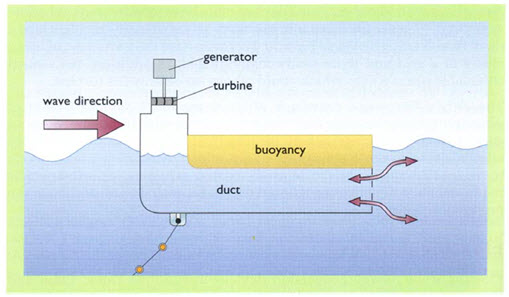
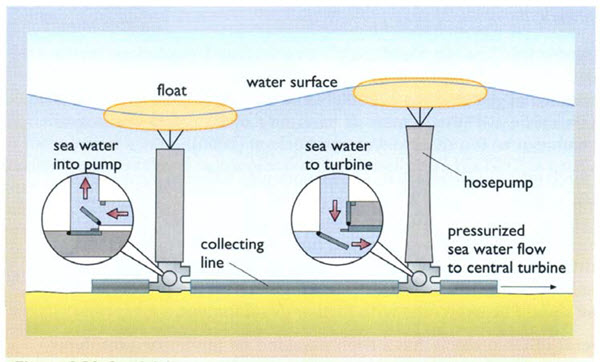
Fig. Schematics of OWC
3.The Pendulum device
The Pendulum device consists of arectangular box, which is open to the seaat one end. A pendulum flap is hingedover this opening, so that the action of thewaves causes it to swing back andforth. This motion is then used to power ahydraulic pump and generator.
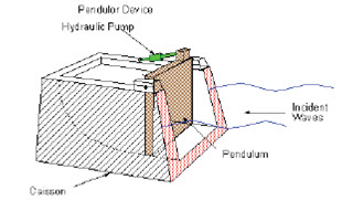
Fig. The Pendulum device
4. Near shore devices - situated in shallow waters, typically 10 - 25 m
5. Off shore devices - situated in deeper water, typically > 40 m
The Danish Wave Power float-pump device uses a float which is attached to a seabed mounted piston pump; the rise and fall motion of the float causes the pump to operate driving a turbine and generator mounted on the pump. The flow of water through the turbine is maintained as unidirectional through the incorporation of a non-return valve.
The Swedish Hose pump has been under development since 1980 It consists of a specially reinforced electrometric hose (whose internal volume decreases as it stretches), connected to a float which rides the waves. The rise and fall of the float stretches and relaxes the hose thereby pressurizing sea water, which is fed (along with the output from other Hose pumps) through a non-return valve to a central turbine and generator unit.
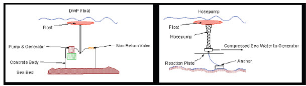
Fig. Danish Wave Power float-pump device Fig. Swedish Hose pump
Ocean Thermal Energy Conversion
Ocean Thermal Energy Conversion (OTEC) is a means of converting into useful energy the temperature difference between surface water of the oceans in tropical and sub-tropical areas, and water at a depth of approximately 1000 m which comes from the polar regions. For OTEC a temperature difference of 20oC is adequate, which embraces very large ocean areas, and favors islands and many developing countries.
Ocean thermal energy conversion (OTEC) is a method which consists of extracting energy from the difference in temperature between shallow and deep waters by way of a heat engine. The biggest difference in temperature (around 20 degrees Celsius, generally located near the equator or tropics), between a heat and cold source provides the greatest amount of potential energy. Thus, the main technical challenge is to generate the most amount of power from a small temperature ratio.
1.Closed Cycle
This cycle uses a working fluid (with a low boiling point) which is cooled down and heated up in a full cycle. The warm water located at the surface is injected into a heat exchanger; the working fluid gets the heat to change its state, and is vaporized. The vapour is directed through the turbine and generator where the electricity is produced. Then the vapor is condensed by the deep cold water. The liquid goes back to the heat exchanger and so on. India has built a closed-cycle, floating plant of 1 MW rated power.
2.Open-cycle
The open-cycle process does not use an intermediate fluid like the closed-cycle but directly uses the sea water. It uses the warm surface in tropical seas. The warm water is placed in a low-pressure container which carries out the evaporation. Like in others cycles, the steam is driven into the turbine attached to a generator. The second effect is the production of desalinated water (fresh water) through evaporation. The steam is condensed into liquid by the deep cold water. Contrary to the first cycle, the
water is captured because it is now clean drinking water
3. Hybrid cycle
The last cycle proposes to combine both open and closed cycles. The warm water is vaporized in a vacuum chamber. The steam transforms working liquid into vapor (heat exchanger) which is directed in a turbine. As in the open-cycle the condensed water provides fresh water.
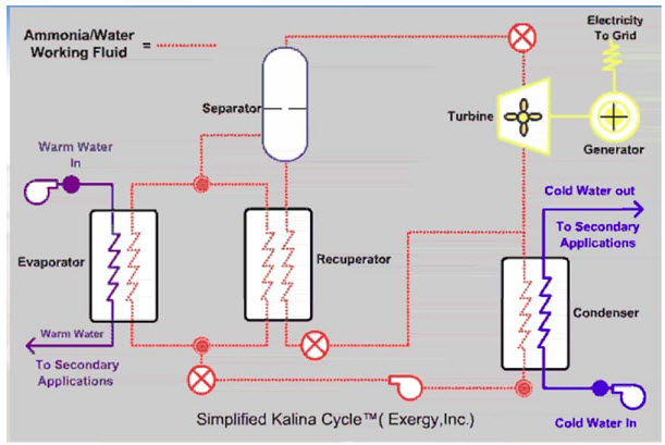
Fig. OTEC Thermodynamic Cycle
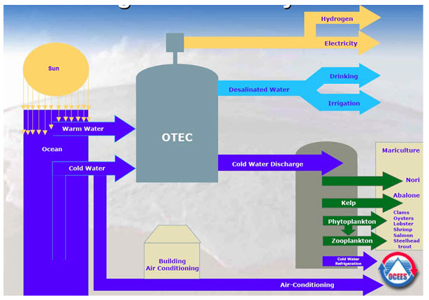
Fig. Integrated OTEC System
Last modified: Thursday, 3 October 2013, 5:25 AM