Site pages
Current course
Participants
General
Module 1 - Water availability and demand and Natio...
Module 2 - Irrigation projects and schemes of India
Module 3 - Concepts and definitions
Module 4 - Command Area Development and Water Mana...
Module 5 - On-Farm-Development works
Module 6 - Water Productivity
Module 7 - Tank & Tube well irrigation
Module 8 - Remote Sensing and GIS in Water Management
Module 9 - Participatory Irrigation Management
Module 10 - Water Pricing & Auditing
LESSON 16. Chak Water Delivery System – Channel Design
Introduction
Assured and timely irrigation water supply to each farm is the basic need for maximizing the agricultural production per unit area of irrigated land in command area. Properly designed and constructed water delivery system only can function efficiently and help to achieve above target. The system should be such that it will supply adequate water efficiently even at peak demand period upto farthest and highest location of each individual farm in command area under the outlet. The system should also be economical.
16.1 Elements of chak water delivery system:
Chak is the area under outlet. Following are the elements of the delivery system.
1) Channel for conveyance of water – to convey water from outlet to farm head.
2) Control structures – to control water distribution and velocities.
3) Crossings - for transportation facilities.
16.1.1 Channels for conveyance:
Channels for conveyance include watercourse and field channel upto farm gate. Equalizer is channel within the farm for internal distribution by the farmer. Field channels convey water from outlet to each farm gate. Watercourse is initial part of field channel near outlet which is dead channel not serving command area.
16.1.2 Planning of Field Channel:
Field channels form the tertiary distribution network in the canal system. These are the last link in the water delivery system of an irrigation network. The planning and design of field channels are, therefore, key issues, which determine the success of an irrigation project. Since the reliability of water supply and credibility of irrigation engineers is dependent on these issues, it is necessary to attend to planning and design of field channels, carefully and judiciously.
16.1.3 Data and maps for planning:
For planning of field channels in particular, following data and maps are necessary:
a) Contour maps of chak to the scale of at least 1:1000 to 1:1250 with contours having an interval of 0.2m to 0.3m. This map shall also show gut numbers and the field boundaries of gut numbers. The natural drains and nallas occurring within the chak shall also be marked on this map.
b) Statement showing names of beneficiaries and their gut numbers with respective ownership area.
c) Type of soil in chak command, as assessed in district soil survey maps. If these maps are not available type of soil shall be decided by taking trial pits.
16.1.4. Field verification of field channel alignment:
Layout and alignment of the field channel network within the chak is obtained as already described in Lec -15, “Chak layout and alignment of field channels.” This layout and alignment of the field channels shall be verified on the field, before detailed survey and actual design of field channels is taken up in hand. This is necessary to accommodate the changes in ownership or division of ownership etc. The field verification of field channel layout helps to modify the alignment to avoid fruit bearing and any other trees or newly dug wells etc. on the F. C. alignment. Secondly, F. C. alignment may also be discussed with beneficiaries / members and office bearers of Water Users’ Association related to the chak. This will be in line with participatory irrigation management and minimize the divergent views taken by beneficiaries during actual construction / taking over the area for management by the W.U.A.
16.1.5 Detailed survey along the alignment of F.C.:
Before the actual design of field channels is taken up in hand, the longitudinal section is run along the alignment recording spot levels at 30m interval. Cross section across the alignment may be taken at 60m interval and at the location of turnouts. The cross section may extend adequately on either side to judge the sill levels of turnouts, with respect to area it has to serve. The L section for each segment of field channel is surveyed separately, with appropriate survey equipments. Trial pits, if necessary, be taken along the alignment of F.C. to access the soil variation and depth of black cotton soils.
16.2 Design of field channels:
The design of field channels envisages design of following three aspects,
a) Discharge
b) Cross section
c) Bed gradient
16.2.1 Design discharge of field channel:
The design prescriptions for the discharge of field channel varies from State to State. The planning commission has prescribed a range of 30 to 70 lit/sec depending upon the type of soil and crops to be served. The Govt. of Maharashtra in Irrigation Department has prescribed design discharge for field channel to be 30 l/s vide Govt. circular CDA-1087/1553/209/87-CAD (LD & Engg) dt. 12th January 1988.
16.2.2 Cross section of field channel:
A trapezoidal cross section of field channel is most suitable for unlined field channels. The design parameters to design a trapezoidal cross section for unlined field channel are as follows:
a) Bed width (B),
b) Side Slope (Z:1, Horizontal : Vertical)
c) Rugosity coefficient (N)
d) Free board (FB)
e) Top width in banking (T)
Typical cross section of unlined field channel is shown in fig. 16.1.
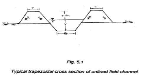
a) Bed width (B):
The bed width of field channel governs the total cross sectional area of field channel to be constructed i.e. it governs the earthwork quantities. It also governs the depth of water flow in the field channel i.e. it governs the driving head at turnout and also the velocity of flow in the field channel. Thus, this is an important dimension from economic as well as hydraulic design point of view. Minimum bed width of 30cm shall be provided in unlined field channel, which caters above requirements. But in very flat topography, this can be increased.
b) Side slope (Z:1, Horizontal : Vertical)
The side slopes for the unlined field channel cross section are designed according to structural stability of soils through which field channel passes. The recommended side slopes in accordance with type of soil are given in Table 16.1.
Table 16.1 Side slopes recommended for unlined field channels
|
Sr. No. |
Type of soil |
Side slope (Horizontal : Vertical) |
|
1. |
Fine Texture Soil (Black cotton soil) |
2½ : 1 |
|
2. |
Medium Texture Soil (Clay loam) |
1½ : 1 |
|
3. |
Coarse Texture soil and soft murum |
1½ : 1 |
|
4. |
Hard Murum |
1 : 1 |
c) Rugosity coefficient (N):
Rugosity coefficient (N) is characteristic of the condition and type of contact surface. For unlined field channels, recommended values of rugosity coefficient (N) are given in Table 16.2.
Table 16.2 Recommended values of N for field channel
|
Sr.No. |
Type of surface |
Recommended values of rugosity coefficient (N) |
|
1 |
Earthen channel |
0.04 |
|
2 |
Earthen channel with grass Soddling |
0.04 |
|
3 |
Rock cuts Hard murum |
0.04 |
|
4 |
UCR masonry lining OR Brick masonry lining |
0.03 |
|
5 |
RCC half round pipe lining |
0.022 |
d) Free board (FB):
Free board is a vertical distance between full supply depth (Y) and the top of retaining banks for field channel. This is necessary for preventing overtopping of banks under unprecedented conditions. For field channel in banking, the minimum free board of 30cm should be kept. For field channels in cutting, the minimum free board shall be about 15 cm to 20 cm, lesser free board may be adopted for field channels in cutting in murum. In case of field channels with R.C.C. half round pipe lining / UCR masonry lining minimum free board shall be 10 cm to 15cm.
e) Top width of section in banking (T):
The field channel cross section may be in full banking or in partial banking – partial cutting. The top width of banking section in such cases may be minimum 0.3 m and may increase upto 0.45 m in accordance with height of banking. Since, the seepage losses through banking are more, the height of banking may not be more than 1.0 m in any case.
16.2.3 Hydraulic design of field channels:
The field channels are designed as unlined, open channels to have a uniform flow. The hydraulic design of field channel is an iterative process to arrive at design discharge with an appropriate bed gradient which generates permissible, non erdodible velocity and results in minimum requirement of drop/falls structures. To determine the bed gradient to suit these requirements, is the key issue in the hydraulic design of field channel. The bed gradient (S) of field channel is the ratio of its vertical drop (H) for a length (L) of channel.
The gradient for each segment of field channel is designed separately. The gradient of field channel should give non-erodible velocity and adequate depth of water to provide sufficient driving head at each turnout to serve maximum area of every farm in the command with minimum land shaping. The maximum permissible gradient consistent with the maximum permissible velocities, shall be adopted wherever required so that the number of drop structures is minimized. To minimize the number of drop structures or falls, ground slope be adopted in the first trial as bed gradient. To obtain the best fit bed gradient for the given segment of field channel, following points are adhered to,
16.2.3.1 Non-erodible velocity:
The velocity in the unlined field channel has to be non-erodible. Hence, the permissible velocities have been recommended in the Table 16.3 for design purposes.
Table 16.3 Permissible velocities in unlined channels in different soils
|
Sr.No. |
Type of Soil Permissible |
Velocity (m/s) |
|
1. |
Silt |
0.45 |
|
2. |
Black cotton soil (Fine texture soils) |
0.5 |
|
3. |
Clay loam |
0.65 |
|
4. |
Soft murum |
0.8 |
|
5. |
Grass sodded section |
0.9 |
|
6. |
Hard murum |
1.0 |
16.2.3.2 Depth of water flow:
The gradient governs the depth of water-flow in the field channel and the depth of water flow in the field channel near turnout with reference to highest ground level in the farm governs the driving head for efficient water distribution through turnout. Hence, the field channel bed gradient should be such that it would evolve a field channel elevation near turnout to get a minimum driving head of 15cm.
16.2.3.3 The design process:
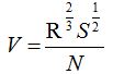
The commonly accepted formula for the hydraulic design of an open channel is Manning’s formula as given below:
 Where,
V = Velocity of flow (m/sec.)
R = hydraulic mean depth = m.
A = Cross sectional area of water flow (m2).
P = Wetted perimeter (m)
S = Bed Gradient
N = Rugosity of coefficient
The typical trapezoidal cross section of unlined field channel is shown in fig. 16.1. The dimensions are decided in accordance with the discussions in 16.2.2.
For the first trial,
1. Assume the natural ground slope along the F C alignment, to be the bed gradient (S) of field channel in that segment, and
2. Assume full supply depth of flow = Y meters. The cross sectional parameters in the Manning’s formula are as below:
B = Bed width of field channel.
Y = Full supply depth
Z = Side slope of trapezoidal cross section of field channel.
A = Wetted cross section area = (B + Z * Y) * Y
P = Wetted perimeter =![]()
R = hydraulic mean depth = ![]() m
m
N = Rugosity of coefficient
S = Bed gradient of field channel
= the natural ground slope in that segment (In the first instance of trial)
Then, using Manning’s formula,
V = velocity of flow =
This trial would be successful & finally accepted for design if,
a. Q is nearly equal to 0.03 cumec.
b. V is within permissible, non-erodible range of velocity for soil type specified in Table 16.3.
c. Y, the full supply depth of flow near turnout is at-least 15cm higher than the ground level in the command of respective turnout. If there is no turnout to be served in the field channel segment, this criteria may be relaxed. If any of these requirements, is not fulfilled, next trial with appropriate depth of flow and bed gradient is conducted as above till the hydraulic and structural requirements of field channel design are satisfied. The calculated values are tabulated table 16.4 to 6 in the end of this lecture for 30 lps discharge and for different side slopes and for N values of 0.022, 0.03 and 0.04.
16.2.4 Longitudinal section of field channel:
The longitudinal section of field channel is finalized as given below. This will facilitate minimum drops/fall or zero drops which will reduce the cost of structure.
1. Plot the ground profile of field channel (main or branch) on L - Section sheet.
2. Mark turnout positions on the L-Section.
3. Divide the whole length of field channel into different reaches/segments having more or less uniform ground slope and workout respective ground slopes.
4. Mark outlet sill level of outlet at the start of FC / WC.
5. Decide bed gradient to be provided to FC / WC. As far as possible natural ground slope be adopted as bed gradient to minimize number of drops / falls. However, care should be taken that bed gradient should neither result in the velocity more than the permissible, nor it should result into full supply depth less than 15cm if turnout is to be served at that chainage. If there is no turnout in a particular reach and strata is hard, bed gradient as steeper as possible (limiting it to natural ground slope) may be adopted even if the full supply depth in F.C. is less than 15cm provided the velocity is within permissible limits.
6. Too many changes in slopes are avoided to ease of construction and better hydraulic conditions.
7. Start marking F.C. bed profile considering designed bed gradient. If the bed gradient is flatter than the ground slope fall / drops will have to be proposed. The location of fall and its depth (bed fall) may be decided considering following guidelines:
a. Fall / drop should not be located U/s of turnouts.
b. The bed level U/s of fall / drop should at least be 10cm in cutting.
c. The depth of drop i.e. bed fall will be governed by the requirement of downstream turnout. Therefore considering downstream turnout, mark the bed profile from downstream turnout going upstream. If necessary more than one fall will have to be provided to avoid excessive height of drop. (i.e. 1 m).
d. Standardized fall / drop designs are available. Where actual bed fall required is different than standard design, the fall as per actual requirement be provided, however the design of next higher fall be adopted (e.g. if fall of 0.4m is necessary, provide 0.4m drop, but the design of 0.45m drop be adopted)
e. Try to provide a sloping bed drop (rapid) wherever F.C. is passing through hard strata like hard murum or soft rock etc. and no turnout is to be served.
16.3 Departure from designed alignment:
To attend better hydraulic functioning of field channels, it is necessary to give the accurate markout as per design and follow the same during construction with proper vigilance. The following tolerances may be accepted in case of construction of field channel during execution:
20 mm on straight section
50 mm on tangents
100 mm on curves
Departure from designed gradient: 20mm
In case of drops, division boxes, turnouts, crossings, the tolerance can be ±20 mm in elevation.
In case of measuring devices, the tolerance can be ± 5mm in elevation and ±5 mm in dimension.
Table No.16.4 Design of Field Channel for 30 lps discharge and bed width of 30 cm and n = 0.022
|
bed width |
normal depth |
side slope |
bed gradient |
n |
Area |
P |
R |
V |
Q |
|
(m) |
(m) |
1 in |
1 in |
|
(sqm) |
m |
|
m/s |
cumec |
|
0.3 |
0.094 |
1.5 |
100 |
0.022 |
0.041454 |
0.638922 |
0.064881 |
0.733264 |
0.030397 |
|
0.3 |
0.113 |
1.5 |
200 |
0.022 |
0.053054 |
0.707427 |
0.074995 |
0.571096 |
0.030299 |
|
0.3 |
0.126 |
1.5 |
300 |
0.022 |
0.061614 |
0.754299 |
0.081684 |
0.493641 |
0.030415 |
|
0.3 |
0.135 |
1.5 |
400 |
0.022 |
0.067838 |
0.786749 |
0.086225 |
0.443215 |
0.030067 |
|
0.3 |
0.143 |
1.5 |
500 |
0.022 |
0.073574 |
0.815594 |
0.090209 |
0.408547 |
0.030058 |
|
0.3 |
0.15 |
1.5 |
600 |
0.022 |
0.07875 |
0.840833 |
0.093657 |
0.382401 |
0.030114 |
|
0.3 |
0.156 |
1.5 |
700 |
0.022 |
0.083304 |
0.862466 |
0.096588 |
0.361387 |
0.030105 |
|
0.3 |
0.162 |
1.5 |
800 |
0.022 |
0.087966 |
0.884099 |
0.099498 |
0.344805 |
0.030331 |
|
0.3 |
0.166 |
1.5 |
900 |
0.022 |
0.091134 |
0.898522 |
0.101427 |
0.329275 |
0.030008 |
|
0.3 |
0.171 |
1.5 |
1000 |
0.022 |
0.095162 |
0.916549 |
0.103826 |
0.317288 |
0.030194 |
|
bed width |
normal depth |
side slope |
bed gradient |
n |
Area |
P |
R |
V |
Q |
|
(m) |
(m) |
1 in |
1 in |
|
(sqm) |
m |
|
m/s |
cumec |
|
0.3 |
0.09 |
2 |
100 |
0.022 |
0.0432 |
0.702492 |
0.061495 |
0.707514 |
0.030565 |
|
0.3 |
0.107 |
2 |
200 |
0.022 |
0.054998 |
0.778519 |
0.070644 |
0.548779 |
0.030182 |
|
0.3 |
0.119 |
2 |
300 |
0.022 |
0.064022 |
0.832184 |
0.076932 |
0.474299 |
0.030366 |
|
0.3 |
0.128 |
2 |
400 |
0.022 |
0.071168 |
0.872433 |
0.081574 |
0.427123 |
0.030397 |
|
0.3 |
0.135 |
2 |
500 |
0.022 |
0.07695 |
0.903738 |
0.085146 |
0.393109 |
0.03025 |
|
0.3 |
0.141 |
2 |
600 |
0.022 |
0.082062 |
0.930571 |
0.088185 |
0.367349 |
0.030145 |
|
0.3 |
0.147 |
2 |
700 |
0.022 |
0.087318 |
0.957404 |
0.091203 |
0.34782 |
0.030371 |
|
0.3 |
0.151 |
2 |
800 |
0.022 |
0.090902 |
0.975293 |
0.093205 |
0.330102 |
0.030007 |
|
0.3 |
0.156 |
2 |
900 |
0.022 |
0.095472 |
0.997653 |
0.095697 |
0.316748 |
0.030241 |
|
0.3 |
0.16 |
2 |
1000 |
0.022 |
0.0992 |
1.015542 |
0.097682 |
0.304637 |
0.03022 |
|
bed width |
normal depth |
side slope |
bed gradient |
n |
Area |
P |
R |
V |
Q |
|
(m) |
(m) |
1 in |
1 in |
|
(sqm) |
m |
|
m/s |
cumec |
|
0.3 |
0.086 |
2.5 |
100 |
0.022 |
0.04429 |
0.763124 |
0.058038 |
0.680726 |
0.030149 |
|
0.3 |
0.103 |
2.5 |
200 |
0.022 |
0.057423 |
0.854672 |
0.067187 |
0.530713 |
0.030475 |
|
0.3 |
0.1132 |
2.5 |
300 |
0.022 |
0.065996 |
0.909601 |
0.072554 |
0.456121 |
0.030102 |
|
0.3 |
0.1215 |
2.5 |
400 |
0.022 |
0.073356 |
0.954298 |
0.076869 |
0.410528 |
0.030115 |
|
0.3 |
0.129 |
2.5 |
500 |
0.022 |
0.080303 |
0.994686 |
0.080731 |
0.379394 |
0.030466 |
|
0.3 |
0.134 |
2.5 |
600 |
0.022 |
0.08509 |
1.021612 |
0.08329 |
0.35362 |
0.03009 |
|
0.3 |
0.139 |
2.5 |
700 |
0.022 |
0.090003 |
1.048538 |
0.085836 |
0.334031 |
0.030064 |
|
0.3 |
0.144 |
2.5 |
800 |
0.022 |
0.09504 |
1.075464 |
0.088371 |
0.318582 |
0.030278 |
|
0.3 |
0.148 |
2.5 |
900 |
0.022 |
0.09916 |
1.097004 |
0.090392 |
0.304925 |
0.030236 |
|
0.3 |
0.152 |
2.5 |
1000 |
0.022 |
0.10336 |
1.118545 |
0.092406 |
0.293561 |
0.030342 |
Table No.16.5 Design of Field Channel for 30 lps discharge and bed width of 30 cm and n = 0.03
|
bed width |
normal depth |
side slope |
bed gradient |
n |
Area |
P |
R |
V |
Q |
|
(m) |
(m) |
1 in |
1 in |
|
(m2) |
m |
|
m/s |
cumec |
|
0.3 |
0.1103 |
1.5 |
100 |
0.03 |
0.051339 |
0.697692 |
0.073584 |
0.584823 |
0.030024 |
|
0.3 |
0.1324 |
1.5 |
200 |
0.03 |
0.066015 |
0.777375 |
0.08492 |
0.455002 |
0.030037 |
|
0.3 |
0.147 |
1.5 |
300 |
0.03 |
0.076514 |
0.830016 |
0.092183 |
0.392411 |
0.030025 |
|
0.3 |
0.1583 |
1.5 |
400 |
0.03 |
0.085078 |
0.870759 |
0.097706 |
0.353286 |
0.030057 |
|
0.3 |
0.1675 |
1.5 |
500 |
0.03 |
0.092334 |
0.90393 |
0.102148 |
0.325499 |
0.030055 |
|
0.3 |
0.1753 |
1.5 |
600 |
0.03 |
0.098685 |
0.932053 |
0.105879 |
0.304335 |
0.030033 |
|
0.3 |
0.1823 |
1.5 |
700 |
0.03 |
0.10454 |
0.957292 |
0.109204 |
0.28763 |
0.030069 |
|
0.3 |
0.1885 |
1.5 |
800 |
0.03 |
0.109848 |
0.979646 |
0.112131 |
0.273842 |
0.030081 |
|
0.3 |
0.194 |
1.5 |
900 |
0.03 |
0.114654 |
0.999477 |
0.114714 |
0.262133 |
0.030055 |
|
0.3 |
0.199 |
1.5 |
1000 |
0.03 |
0.119102 |
1.017505 |
0.117053 |
0.252051 |
0.03002 |
|
bed width |
normal depth |
side slope |
bed gradient |
n |
Area |
P |
R |
V |
Q |
|
(m) |
(m) |
1 in |
1 in |
|
(m2) |
m |
|
m/s |
cumec |
|
0.3 |
0.1047 |
2 |
100 |
0.03 |
0.053334 |
0.768233 |
0.069425 |
0.562559 |
0.030004 |
|
0.3 |
0.1249 |
2 |
200 |
0.03 |
0.06867 |
0.85857 |
0.079982 |
0.437179 |
0.030021 |
|
0.3 |
0.1383 |
2 |
300 |
0.03 |
0.079744 |
0.918496 |
0.08682 |
0.377031 |
0.030066 |
|
0.3 |
0.1484 |
2 |
400 |
0.03 |
0.088565 |
0.963665 |
0.091904 |
0.339152 |
0.030037 |
|
0.3 |
0.1568 |
2 |
500 |
0.03 |
0.096212 |
1.001231 |
0.096094 |
0.312502 |
0.030067 |
|
0.3 |
0.1638 |
2 |
600 |
0.03 |
0.102801 |
1.032536 |
0.099562 |
0.292099 |
0.030028 |
|
0.3 |
0.17 |
2 |
700 |
0.03 |
0.1088 |
1.060263 |
0.102616 |
0.275937 |
0.030022 |
|
0.3 |
0.1756 |
2 |
800 |
0.03 |
0.114351 |
1.085307 |
0.105363 |
0.262703 |
0.03004 |
|
0.3 |
0.1806 |
2 |
900 |
0.03 |
0.119413 |
1.107668 |
0.107806 |
0.251495 |
0.030032 |
|
0.3 |
0.1852 |
2 |
1000 |
0.03 |
0.124158 |
1.12824 |
0.110046 |
0.241885 |
0.030032 |
|
bed width |
normal depth |
side slope |
bed gradient |
n |
Area |
P |
R |
V |
Q |
|
(m) |
(m) |
1 in |
1 in |
|
(m2) |
m |
|
m/s |
cumec |
|
0.3 |
0.1004 |
2.5 |
100 |
0.03 |
0.05532 |
0.840671 |
0.065805 |
0.542822 |
0.030029 |
|
0.3 |
0.1192 |
2.5 |
200 |
0.03 |
0.071282 |
0.941912 |
0.075678 |
0.421342 |
0.030034 |
|
0.3 |
0.1316 |
2.5 |
300 |
0.03 |
0.082776 |
1.008688 |
0.082063 |
0.363125 |
0.030058 |
|
0.3 |
0.141 |
2.5 |
400 |
0.03 |
0.092003 |
1.059308 |
0.086851 |
0.326598 |
0.030048 |
|
0.3 |
0.1486 |
2.5 |
500 |
0.03 |
0.099785 |
1.100235 |
0.090694 |
0.300676 |
0.030003 |
|
0.3 |
0.1552 |
2.5 |
600 |
0.03 |
0.106778 |
1.135778 |
0.094013 |
0.281137 |
0.030019 |
|
0.3 |
0.161 |
2.5 |
700 |
0.03 |
0.113103 |
1.167012 |
0.096916 |
0.265617 |
0.030042 |
|
0.3 |
0.1662 |
2.5 |
800 |
0.03 |
0.118916 |
1.195014 |
0.09951 |
0.252878 |
0.030071 |
|
0.3 |
0.1708 |
2.5 |
900 |
0.03 |
0.124172 |
1.219786 |
0.101798 |
0.242058 |
0.030057 |
|
0.3 |
0.1749 |
2.5 |
1000 |
0.03 |
0.128945 |
1.241865 |
0.103832 |
0.232686 |
0.030004 |
Table No.16.6 Design of Field Channel for 30 lps discharge and bed width of 30 cm and n = 0.04
|
bed width |
normal depth |
side slope |
bed gradient |
n |
Area |
P |
R |
V |
Q |
|
(m) |
(m) |
1 in |
1 in |
|
(m2) |
m |
|
m/s |
cumec |
|
0.3 |
0.1285 |
1.5 |
100 |
0.04 |
0.063318 |
0.763313 |
0.082952 |
0.475114 |
0.030083 |
|
0.3 |
0.1535 |
1.5 |
200 |
0.04 |
0.081393 |
0.853452 |
0.09537 |
0.368716 |
0.030011 |
|
0.3 |
0.1702 |
1.5 |
300 |
0.04 |
0.094512 |
0.913665 |
0.103443 |
0.317822 |
0.030038 |
|
0.3 |
0.1829 |
1.5 |
400 |
0.04 |
0.105049 |
0.959455 |
0.109488 |
0.285869 |
0.03003 |
|
0.3 |
0.1934 |
1.5 |
500 |
0.04 |
0.114125 |
0.997314 |
0.114433 |
0.263335 |
0.030053 |
|
0.3 |
0.2022 |
1.5 |
600 |
0.04 |
0.121987 |
1.029042 |
0.118544 |
0.246118 |
0.030023 |
|
0.3 |
0.21 |
1.5 |
700 |
0.04 |
0.12915 |
1.057166 |
0.122166 |
0.232481 |
0.030025 |
|
0.3 |
0.217 |
1.5 |
800 |
0.04 |
0.135734 |
1.082405 |
0.1254 |
0.221289 |
0.030036 |
|
0.3 |
0.2232 |
1.5 |
900 |
0.04 |
0.141687 |
1.104759 |
0.128252 |
0.211786 |
0.030007 |
|
0.3 |
0.229 |
1.5 |
1000 |
0.04 |
0.147362 |
1.125671 |
0.13091 |
0.203686 |
0.030015 |
|
bed width |
normal depth |
side slope |
bed gradient |
n |
Area |
P |
R |
V |
Q |
|
(m) |
(m) |
1 in |
1 in |
|
(m2) |
m |
|
m/s |
cumec |
|
0.3 |
0.1213 |
2 |
100 |
0.04 |
0.065817 |
0.84247 |
0.078124 |
0.456487 |
0.030045 |
|
0.3 |
0.1441 |
2 |
200 |
0.04 |
0.08476 |
0.944435 |
0.089746 |
0.354069 |
0.030011 |
|
0.3 |
0.1593 |
2 |
300 |
0.04 |
0.098543 |
1.012411 |
0.097335 |
0.305179 |
0.030073 |
|
0.3 |
0.1706 |
2 |
400 |
0.04 |
0.109389 |
1.062946 |
0.102911 |
0.274297 |
0.030005 |
|
0.3 |
0.1801 |
2 |
500 |
0.04 |
0.118902 |
1.105432 |
0.107562 |
0.25268 |
0.030044 |
|
0.3 |
0.1881 |
2 |
600 |
0.04 |
0.127193 |
1.141209 |
0.111455 |
0.2362 |
0.030043 |
|
0.3 |
0.195 |
2 |
700 |
0.04 |
0.13455 |
1.172067 |
0.114797 |
0.223031 |
0.030009 |
|
0.3 |
0.2015 |
2 |
800 |
0.04 |
0.141655 |
1.201135 |
0.117934 |
0.212411 |
0.030089 |
|
0.3 |
0.207 |
2 |
900 |
0.04 |
0.147798 |
1.225732 |
0.120579 |
0.203249 |
0.03004 |
|
0.3 |
0.2121 |
2 |
1000 |
0.04 |
0.153603 |
1.24854 |
0.123026 |
0.195419 |
0.030017 |
|
bed width |
normal depth |
side slope |
bed gradient |
n |
Area |
P |
R |
V |
Q |
|
(m) |
(m) |
1 in |
1 in |
|
(m2) |
m |
|
m/s |
cumec |
|
0.3 |
0.1158 |
2.5 |
100 |
0.04 |
0.068264 |
0.923602 |
0.073911 |
0.439914 |
0.03003 |
|
0.3 |
0.137 |
2.5 |
200 |
0.04 |
0.088023 |
1.037768 |
0.084819 |
0.340981 |
0.030014 |
|
0.3 |
0.151 |
2.5 |
300 |
0.04 |
0.102303 |
1.11316 |
0.091903 |
0.293711 |
0.030047 |
|
0.3 |
0.1615 |
2.5 |
400 |
0.04 |
0.113656 |
1.169704 |
0.097166 |
0.263987 |
0.030004 |
|
0.3 |
0.171 |
2.5 |
500 |
0.04 |
0.124403 |
1.220863 |
0.101897 |
0.243724 |
0.03032 |
|
0.3 |
0.1776 |
2.5 |
600 |
0.04 |
0.132134 |
1.256405 |
0.105169 |
0.227228 |
0.030025 |
|
0.3 |
0.184 |
2.5 |
700 |
0.04 |
0.13984 |
1.29087 |
0.10833 |
0.21457 |
0.030005 |
|
0.3 |
0.19 |
2.5 |
800 |
0.04 |
0.14725 |
1.323181 |
0.111285 |
0.204347 |
0.03009 |
|
0.3 |
0.195 |
2.5 |
900 |
0.04 |
0.153563 |
1.350107 |
0.113741 |
0.195486 |
0.030019 |
|
0.3 |
0.2 |
2.5 |
1000 |
0.04 |
0.16 |
1.377033 |
0.116192 |
0.18811 |
0.030098 |
Last modified: Tuesday, 18 February 2014, 8:16 AM