Site pages
Current course
Participants
General
MODULE 1.
MODULE 2.
MODULE 3.
MODULE 4.
MODULE 5.
MODULE 6.
MODULE 7.
MODULE 8.
MODULE 9.
Topic 10
Lesson 4. COMPASS TRAVERSING
4.1 INTRODCTION AND PURPOSE
In chain surveying, the area to be surveyed is divided into a number of triangles. This method is suitable for fairly level ground covering small areas. But when the area is large, undulating and crowded with many details, triangulation (which is the principle of chain survey) is not possible. In such an area, the method of traversing is adopted.
In traversing, the framework consists of a number of connected lines. The lengths are measured by chain or tape and the directions identified by angle measuring instruments. In one of the methods, the angle measuring instrument used is the compass. Hence, the process is known as compass traversing.
Note: Consideration of the traverse in an anticlockwise direction is always convenient in running the survey lines.
4.2 DEFINITIONS
1.True meridian The line or plane passing through the geographical north pole, geographical south pole and any point on the surface of the earth, is known as the ‘true meridian’ or ‘geographical merdian’. The true meridian at a station is constant. The true meridians passing through different points on the earth’s surface are not parallel, but converge towards the poles.
But for surveys is small areas, the true meridians passing through different points are assumed parallel.
The angle between the true meridian and a line is known as ‘true bearing’ of the line. It is also known as the ‘azimuth’.
2. Magnetic meridian When a magnetic needle is suspended freely and balanced properly, unaffected by magnetic substances, it indicates a direction. This direction is known as the ‘magnetic meridian’.
The angle between the magnetic meridian and a line is known as the ‘magnetic bearing’ or simply the ‘bearing’ of the line
3. Arbitrary meridian Sometimes for the survey of small area, a convenient direction is assumed as a meridian, known as the ‘arbitrary meridian’. Sometimes the starting line of a survey is taken as the arbitrary meridian.
The angle between the arbitrary meridian and a line is known as the ‘arbitrary bearing’ of the line.
4. Grid meridian Sometimes, for preparing a map some state agencies assume several lines parallel to the true meridian for a particular zone. These lines are termed as ‘grid lines’ and the central line the ‘grid meridian’. The bearing of a line with respect to the grid meridian is known as the ‘grid bearing’ of the line.
5. Designation of magnetic bearing Magnetic bearings are designated by two systems :
(i) Whole circle bearing (WCB), and
(ii) Quadrantal bearing (QB).
(a) Whole Circle Bearing (WCB) The magnetic bearing of a line measured clockwise from the north pole towards the line, is known as the ‘whole circle bearing’, of that line. Such a bearing may have any value between 00 and 3600. The whole circle bearing of a line is obtained by prismatic compass
For example,
WCB of AB = θ1
WCB of AC = θ2
WCB of AD = θ3
WCB of AE = θ4
(b) Quadrantal Bearing (QB)The magnetic bearing of a line measured clockwise or counterclockwise from the North Pole or South Pole (whichever is nearer the line) towards the East or West, is known as the ‘quadrantal bearing’ of the line. This system consists of four quadrant) Quardrantal Bearing (QB s – NE, SE, SW and NW. The value of a quadrantal bearing lies between 00 and 900, but the quadrants should always be mentioned. Quadrantal bearings are obtained by the surveyor’s compass
For example, QB of AB = N
6. Reduced bearing (RB) When the whole circle bearing of a line is converted to quadrantal bearing. It is termed the ‘reduced bearing’. Thus, the reduced bearing is similar to the quadrantal bearing. Its value lies between 00 and 900, but the quadrants should be mentioned for proper designation.
7. Fore and back bearing The bearing of a line measured in the direction of the progress of survey is called the ‘fore bearing’ (FB) of the line.
The bearing of a line measured in the direction opposite to the survey is called the ‘back bearing’ (BB) of the line
For example, FB of AB = θ
BB of AB = θ1
Remember the following:
(a) In the WCB system, the difference between the FB and BB should be exactly 1800, and the negative sign when it is more than 1800. Remember the following relation:
BB = FB ± 1800
Use the positive sign when FB is less than 1800, and the negative sign when it is more than 1800.
(b) In the quandrantal bearing (i.e. reduced bearing) system, the FB and B3 are numerically equal but the quadrants are just opposite.
For example, if the FB of AB is N 300 E, then its BB is S 300 W.
8. Magnetic declination The horizontal angle between the magnetic meridian and true meridian is known as ‘magnetic declination’.
When the north end of the magnetic needle is pointed towards the west side of the true meridian, the position is termed ‘Declination West’ ().
When the north end of the magnetic needle is pointed towards the east side of the true meridian, the position is termed ‘Declination East’
9. Isogonic and agonic lines Lines passing through points of equal declination are known as ‘isogonic’ lines.
The Survey of India Department has prepared a map of India in which the isogonic and agonic lines are shown properly as a guideline to conduct the compass survey in different parts of the country.
10. Variation of magnetic declination The magnetic declination at a place is not constant. It varies due to the following reasons:
(a) Secular Variation The magnetic meridian behaves like a pendulum with respect to the true meridian. After every 100 years or so, it swings from one direction to the opposite direction, and hence the declination varies. This variation is known as ‘secular variation’.
(b) Annual Variation The magnetic declination varies due to the rotation of the earth, with its axis inclined, in an elliptical path around the sun during a year. This variation is known as ‘annual variation. The amount of variation is about 1 to 2 minutes.
(c) Diurnal Variation The magnetic declination varies due to the rotation of the earth on its own axis in 24 hours. This variation is known as ‘dirunal variation’. The amount of variation is found to be about 3 to 12 minutes.
(d) Irregular Variation The magnetic declination is found to vary suddenly due to some natural causes, such as earthequakes, volcanic eruptions and so on. This variation is known as ‘irregular variation’.
11. Dip of the magnetic needle If a needle is perfectly balanced before magnetisation, it does not remain in the balanced position after it is magnetised. This is due to the magnetic influence of the earth. The needle is found to be inclined towards the pole. This inclination of the needle with the horizontal is known as the ‘dip of the magnetic needle’.
It is found that the north end of the needle is deflected downwards in the northern hemisphere and that is south end is deflected downwards in the southern hemisphere. The needle is just horizontal at the equator. To balance the dip of the needle, a rider (brass or silver coil) is provided along with it. The rider is placed over the needle at a suitable position to make it horizontal.
12. Local attraction A magnetic needle indicates the north direction when freely suspended or pivoted. But if the needle comes near some magnetic substances, such as iron ore, steel structures, electric cables conveying current; etc. it is found to be deflected from its true direction, and does not show the actual north. This disturbing influence of magnetic substances is known as ‘local attraction’.
To detect the presence of local attraction, the fore and back bearings of a line should be taken. If the difference of the fore and back bearings of the line is exactly 1800, then there is no local attraction.
If the FB and BB of a line do not differ by 1800, then the needle is said to be affected by local attraction, provided there is no instrumental error.
To compensate for the effect of local attraction, the amount of error is found out and is equally distributed between the fore and back bearings of the line.
For example, consider the case when
Observed FB of AB = 60030’
Observed BB of AB = 24000’
Calculated BB of AB = 600300 + 18000’ = 240030’
Corrected BB of AB = 1/2 (24000’ + 240030’) = 240015’
Hence, Corrected FB of AB = 240015’ – 18000’ = 60015’
13. Method of application of correction
(a) First Method The interior angles of a traverse are calculated from the observed bearings. Then an angular check is applied. The sum of the interior angles should be equal to (2n – 4) x 900 (n being the number of sides of the traverse). If it is not so, the total error is equally distributed among all the angles of the traverse.
Then, starting from the unaffected line, the bearings of all the lines may be corrected by using the corrected interior angles. This method is very laborious and is not generally employed.
(b) Second Method In this method, the interior angles are not calculated. From the given table, the unaffected line is first detected. Then, commencing from the unaffected line, the bearings of the other affected lines are corrected by finding the amount of correction at each station.
This is an easy method, and one which is generally employed.
Note: If all the lines of a traverse are found to be affected by local attraction, the line with minimum error is identified. The FB and BB of this line are adjusted by distributing the error equally. Then, starting from this adjusted line, the fore and back bearing of other lines are corrected.
4.3. PRINCIPLE OF COMPASS SURVEYING
The principle of compass surveying is traversing, which involves a series of connected lines. The magnetic bearings of the lines are measured by prismatic compass and the distances of the lines are measured by chain. Such survey does not require the formation of a network of triangles.
Interior details are located by taking offsets from the main survey lines. Sometimes subsidiary lines may be taken for locating these details.
Compass surveying is not recommended for areas where local attraction is suspected due to the presence of magnetic substances like steel structures, iron ore deposits, electric cables conveying current, and so on.
4.4 TRAVERSING
As already stated in the last section, surveying which involves a series of connected lines is known as ‘traversing.’ The sides of the traverse are known as ‘traverse legs’.
In traversing, the lengths of the lines are measured by chain and the directions are fixed by compass or theodolite or by forming angles with chain and tape.
A traverse may be of two types – closed and open.
1. Closed traverse When a series of A connected lines forms a closed circuit, i.e. when the finishing point coincides with the starting point coincides with the starting point of a survey, it is called a ‘closed traverse’. Here ABCDEA represents a closed traverse. Closed traverse is suitable for the survey of boundaries of ponds, forests estates, etc.
2. Open traverse When a sequence of connected lines extends along a general direction and does not return to the starting point, it is known as ‘open traverse’ or ‘unclosed traverse’. Here ABCDE represents an open traverse
Open traverse is suitable for the survey of roads, rivers, coast lines, etc.
4.5 MEHODS OF TRAVERSING
Traverse survey may be conducted by the following methods :
Chain traversing (by chain angle)
Compass traversing (by free needle)
Theodolite traversing (by fast needle) and
Plane table traversing (by plane table)
1.Chain traversing Chain traversing is mainly conducted when it is not possible to adopt triangulation. In this method, the angles between adjacent sides are fixed by chain angles. The entire survey is conducted by chain and tape only and no angular measurements are taken. When it is not possible to form triangles, as, for example, in a pond, chain traversing is conducted,
The formation of chain angles is
(a) First Method Suppose a chain angle is to be formed to fix the directions of sides AB and AD. Tie stations T1 and T2 are fixed on lines AB and AD. The distances AT1, AT2 and T1T2 are measured. Then the angle T1AT2 is said to be the chain angle. So, the chain angle is fixed by the tie line T1T2.
(b) Second Method Sometimes the chain angle is fixed by chord. Suppose the angle between the lines AB and AC is to be fixed. Taking A as the centre and a radius equal to one tape length (15 m), an arc intersecting the lines AB and AC at points P and Q, respectively, is drawn. The chord PQ is measured and bisected at R.
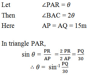
The angle θ can be calculated from the above equation, and the chain angle BAC can be determined accordingly.
2. Compass traversing In this method, the fore and back bearings of the traverse legs are measured by prismatic compass and the sides of the traverse by chain or tape. Then the observed bearings are verified and necessary corrections for local attraction are applied. In this method, closing error may occur when the traverse is plotted. This error is adjusted graphically by using ‘Bowditch’s rule’ (which is described later on).
3. Theodolite traversing In such traversing, the horizontal angles between the traverse legs are measured by theodolite. The lengths of the legs are measured by chain or by employing the stadia method. The magnetic bearing of the starting leg is measured by theodolite. Then the magnetic bearings of the other sides are calculated. The independent coordinates of all the traverse stations are then found out. This method is very accurate.
4. Plane table traversing In this method, a plane table is set at every traverse station in the clockwise or anticlockwise direction, and the circuit is finally closed. During traversing, the sides of the traverse are plotted according to any suitable scale. At the end of the work, any closing error which may occur is adjusted graphically.
4.6. CHECK ON CLOSED TRAVERSE
1. Check on angular measurements
(a) The sum of the measured interior angles should be equal to (2N – 4) x 900 where N is the number of sides of the traverse.
(b) The sum of the measured exterior angles should be equal to (2N + 4) x 900.
(c) The algebraic sum of the deflection angles should be equal to 3600.
Right-hand deflection is considered positive and left-hand deflection negative.
2. Check on linear measurement
(a) The lines should be measurement once each on two different days (along opposite directions). Both measurements should tally.
(b) Linear measurements should also be taken by the stadia method. The measurements by chaining and by the stadia method should tally.
4.7 CHECK ON OPEN TRAVERSE
In open traverse, the measurements cannot be checked directly. But some field measurements can be taken to check the accuracy of the work. The methods are discussed below.
1. Taking cut-off lines Cut-off lines are taken between some intermediate stations of the open traverse. Suppose ABCDEF represents an open traverse. Let AD and DG be the cut-off lines. The lengths and magnetic bearings of the cut-off lines are measured accurately. After plotting the traverse, the distances and bearings are noted from the map. These distances and bearings should tally with the actual records from the field
2. Taking an auxiliary point Suppose ABCDEF is an open traverse. A permanent point P is selected on one side of it. The magnetic bearings of this point are taken from the traverse stations A,B,C,D, etc. If the survey is carried out accurately and so is the plotting, all the measured bearings of P when plotted should meet at the point P. The permanent point P is known as the ‘auxiliary point’
4.8 TYPES OF COMPASS
There are two types of compass:
The prismatic compass, and
The surveyor’s compass.
1. The prismatic compass In this compass, the readings are taken with the help of a prism. The following are the essential parts of this compass:
(a) Compass Box The compass box is a circular metallic box (the metal should be non-magnetic) of diameter 8 to 10 cm. A pivot with a sharp point is provided at the centre of the box.
(b) Magnetic Needle and Graduated Ring The magnetic needle is made of a broad, magnetised iron bar. The bar is pointed at both ends. The magnetic needle is attached to a graduated aluminium ring.
The ring is graduated from 00 to 3600 clockwise, and the graduations begin from the south end of the needle. Thus 00 is marked at the south, 900 at the west, 1800 at north and 2700 at the east. The degrees are again subdivided into half-degrees. The figures are written upside down. The arrangement of the needle and ring contains an agate cap pivoted on the central pivot point. A rider of brass or silver coil is provided with the needle to counterbalance its dip.
(c) Sight Vane and Prism The sight vane and the reflecting prism are fixed diametrically opposite to the box. The sight vane is hinged with the metal box and consists of a horsehair at the centre. The prism consists of a sighting slit at the top and two small circular holes, one at bottom of the prism and the other at the side of the observer’s eye.
(d) Dark Glasses Two dark glasses are provided with the prism. The red glass is meant for sighting luminous objects at night and the blue glass for reducing the strain on the observer’s eye in bright daylight.
(e) Adjustable Mirror A mirror is provided with the sight vane. The mirror can be lowered or raised, and can also be inclined. If any object is too low or too high with respect to the line of sight, the mirror can be adjusted to observe it through reflection.
(f) Brake Pin A brake pin is provided just at the base of the sight vane. If pressed gently, it stops the oscillations of the ring.
(g) Lifting Pin A lifting pin is provided just below the sight vane. When the sight vane is folded, it presses the lifting pin. The lifting pin then lifts the magnetic needle out of the pivot point to prevent damage to the pivot head.
(h) Glass Cover A glass cover is provided on top of the box to protect the aluminium ring from dust
2. The Surveyor’s compass The surveyor’s compass is similar to the prismatic compass except for the following points.
(a) There is no prism on it. Readings are taken with naked eye.
(b) It consists of an eye-vane (in place of prism) with a fine sight slit.
(c) The graduated aluminium ring is attached to the circular box. It is not fixed to the magnetic needle.
(d) The magnetic needle moves freely over the pivot. The needle shows the reading on the graduated ring.
(e) The ring is graduated from 00 to 900 in four quadrants. 00 is marked at the north and south, and 900 at the east and west. The letters E (east) and W (west) are interchanged from their true positions. The figures are written the right way up.
(f) No mirror is attached to the object vane.
4.9 TEMPORARY ADJUSTMENT OF PRISMATIC COMPASS (FIELD PROCEDURE OF OBSERVING BEARING)
The following procedure should be adopted while measuring the bearing by prismatic compass.
Fixing the compass with tripod stand The tripod stand is placed at the required station with its legs well apart. Then the prismatic compass is held by the left hand and placed over the threaded top of the stand. After this, the compass box is turned clockwise by the right hand. Thus the threaded base of the compass box is fixed with the threaded top of the stand.
Centering Normally, the compass is centred by dropping a piece of stone from the bottom of the compass box. Centring may also be done with the aid of a plumb bob held centrally below the compass box.
Levelling: Levelling is done with the help of a ball-and-socket arrangement provided on top of the tripod stand. This arrangement is loosened and the box is placed in such a way that the graduated ring rotates freely without touching either the bottom of the box or the glass cover on top.
Adjustment of prism: the prism is moved up and down till the figures on the graduated ring are seen sharp and clear.
Observation of bearing: After centering and leveling the compass box over the station, the ranging rod at the required station is bisected perfectly by sighting through the slit of the prism and horsehair at the sight vane.
At this time the graduated ring may rotate rapidly. The brake pin is pressed very gently to stop this rotation. When the ring comes to rest, the box is struck very lightly to verify the horizontality of the ring and the frictional effect on the pivot point. Then the reading is taken from the graduated ring through the hole in the prism. This reading will be magnetic bearing of the line.
Last modified: Wednesday, 30 October 2013, 9:09 AM