Site pages
Current course
Participants
General
MODULE 1.
MODULE 2.
MODULE 3.
MODULE 4.
MODULE 5.
MODULE 6.
MODULE 7.
MODULE 8.
MODULE 9.
Topic 10
Lesson 16. Introduction to setting of curves
Curves are regular bends provided in the lines of communication like roads, railways and canals etc. to bring about gradual change of direction.
They enable the vehicle to pass from one path on to another when the two paths meet at an angle. They are also used in the vertical plane at all changes of grade to avoid the abrupt change of grade at the apex.
HORIZONTAL CURVES
Curves provided in the horizontal plane to have the gradual change in direction are known as horizontal curves.
VERTICAL CURVES
Curves provided in the vertical plane to obtain the gradual change in grade are called as vertical curves.
Curves may be circular or parabolic. Curves are generally arcs of parabolas.
Curves are laid out on the ground along the centre line of the work.
NEED FOR PROVIDING CURVES
Curves are needed on Highways, railways and canals for bringing about gradual change of direction of motion. They are provided for following reasons:-
i) To bring about gradual change in direction of motion.
ii) To bring about gradual change in grade and for good visibility.
iii) To alert the driver so that he may not fall asleep.
iv) To layout Canal alignment.
v) To control erosion of canal banks by the thrust of flowing water in a canal.
CLASSIFICATION OF CURVES
Most types of transportation routes, such as highways, railroads, and pipelines, are connected by curves in both horizontal and vertical planes.
Horizontal Curves: Curves used in horizontal planes to connect two straight tangent sections.
Two types of horizontal cures:
Circular arcs, and
Spirals
Simple Curve: A circular arc connecting two tangents.
Compound Curve: Two or more circular arcs of different radii tangent to each other.
Broken-back Curve: Combination of a short length of tangent connecting two circular arcs that have centers on the same side.
Reverse Curve: Two circular arcs tangent to each other, with their centers on opposite side of the alignment.
Circular curves are further classified as :
Simple Curves.
Compound Curves.
Serpentine Curves.
Deviation Curves.
1. Simple Curve:
A simple curve Consists of a single arc of circle connecting two straights. It has radius of the same magnitude throughout.
2. Compound Curves.
A compound Curve consists of two or more simple curves having different radii bending in the same direction and lying on the same side of the common tangent. Their centres lie on the same side of the curve.
3. Reverse or serpentine curve
A reverse or serpentine curve is made up of two arcs having equal or different radii bending in opposite direction with a common tangent at their junction . Their centres lie on opposite sides of the curve. Reverse curves are used when the straights are parallel or intersect at a very small angle.
4. Deviation curve
A deviation curve is simply a combination of two reverse curves. it is used when it becomes necessary to deviate from a given straight path in order to avoid intervening obstructions such as bend of river, a building , etc.
They should be avoided as far as possible on main lines and highways where speeds are necessarily high.
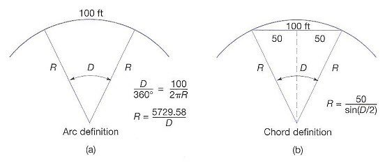
Degree of Circular Curve
The rate of curvature of circular curves can be designated either by their radius (100-m curve), or by their degree of curve.
The degree of curve:
Arc definition: The central angle subtended by a circular arc of 30m (100-ft).
Chord definition: The angle at the center of a circular arc subtended by a chord of 30m (100 ft).
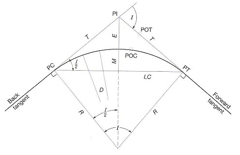
Definitions and Derivation of Circular Curve Formulas (Ref Fig.)
PI: Point of intersection
PC: Point of curvature (the beginning of the curve)
PT: Point of tangency (the end of the curve)
TC: Tangent to curve
CT: Curve to tangent
R: Curve radius
T: Tangent distance (PC-PI or PI-PT)
LC: Long chord (PC-PT)
L: Length of the curve (along the curve)
E: Length from the PI to the curve midpoint on a radial line.
M: Middle ordinate. The radial distance from the midpoint of the long chord to the curves midpoint.
POC: Any point on curve.
POT: Any point on tangent.
Da: Degree of any curve (arc definition)
Dc: Degree of any curve (chord definition)
I: Intersection angle (central angle)
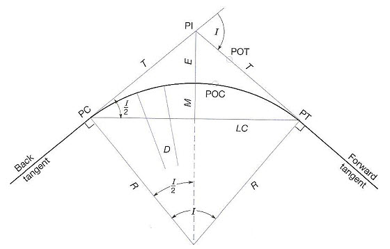
FIG. CIRCULAR CURVE ELEMENTS
Stationing
Stationing: In route surveying, stationing is used to specify the relative horizontal positioning of any point along the reference line. The starting point is usually designated with some arbitrary value.
English Unit System:
Starting point: Usually 10 + 00 ft or 100 + 00 ft is selected.
Metric Unit System:
Starting point: Usually 1 + 000 km or 10 + 00 km is selected. In rural areas, the spacing is usually taken as 10, 20, 30, and 40m.
Circular Curve Stationing
The beginning point of any project is assign a station value, and all other points along the reference line are then related to it.
After the tangents have been staked and stationed, the I angle is observed at each PI, and curves computed and staked.
General Procedure of Circular Curve Layout by Deflection Angles
Layout of a curve by deflection angles can be done by
The incremental chord method, and
The total chord method
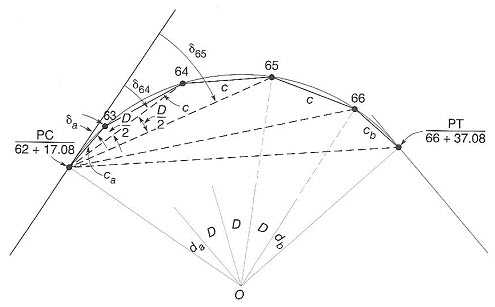
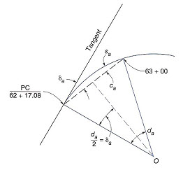
FIG Circular Curve Layout by Deflection Angles
Layout of a curve by the incremental chord method:
Assume that the instrument is set up over the PC and each full station is to be marked along the curve.
The first station to be set in this example is 63 + 00.
To mark that point form the PC, a backsight is taken on the PI with zero set on the instrument’s horizontal circle.
Deflection angle δa to station 63 + 00 is then turned and two tape persons measure chord ca from the PC and set 63 + 00 at the end of the chord on the instrument’s line of sight.
With station 63 + 00 set, the tape persons next measure the chord length c from it and stake station 64 + 00, where the line of sight of the instrument , now set to δ64, intersects the end of that chord.
This process is repeated until the entire curve is laid out.
Layout of a curve by the total chord method:
The total station instrument is set up over the PC and each full station is to be marked along the curve.
The first station to be set in this example is 63 + 00.
To mark that point form the PC, a backsight is taken on the PI with zero set on the total station’s horizontal circle.
Deflection angle δa to station 63 + 00 is then turned and the reflector placed on line and adjusted until its distance from the instrument is ca from the PC and the stake set at 63 + 00.
To set station 64 + 00, the deflection angle δ64 is turned, reflector placed on this line of sight, and adjusted in position until the total chord from the PC to station 64 + 00 is obtained, and the stake set.
This process is repeated until the entire curve is laid out.
 Computing Deflection Angles and Chords
For deflection angle method, deflection angles and chords are important values that must be calculated.
To stake the first station,which is normally an odd
distance from the PC (shorter than a full-station increment), subdeflection angle δa and subchord ca are needed.
Central angle da subtended by arc sa from the PC to 63 + 00 is calculated by proportion
da/sa = I/L from which da= sa I / L
Theorem: The angle at a point between a tangent and any chord is equal to half the central angle subtended by the chord.
-
Thus subdeflection angle δa needed to stake station 63 + 00 is da/2, or da= sa I / 2L.
Last modified: Friday, 6 December 2013, 6:20 AM