Site pages
Current course
Participants
General
Module 1. Introduction to Theory of Machine
Module 2. Planar Mechanism
Module 3. Velocity and Acceleration Analysis
Topic 4
Topic 5
Topic 6
Topic 7
Topic 8
Topic 9
Topic 10
Lesson 2. Planer Mechanism
2.1 LINK
A link is defined as a single part which can be a resistant body or a combination of resistant bodies having inflexible connections and having a relative motion with respect to other parts of the machine. A link is also known as kinematic link or element. Links should not be confused with the parts of the mechanism. Different parts of the mechanism can be considered as single link if there is no relative motion between them.
Example: The frame of any machine is considered as single link as there is no relative motion between the various parts of the frame. As shown in slider crank mechanism shown below, the frame is considered as one link (link 1) as there is no relative motion in frame itself. The crank here is link 2 & connecting rod is again single link (link 3). The slider or piston is link 4 as there is no relative motion it. In this way, many complex mechanisms can be describe by simple configuration diagram by considering the definition of a link.
 Fig: 2.1 Slider crank mechanism
2.1.1 TYPES OF LINKS: Links can be classified into Binary, Ternary, Quaternary etc. depending upon its ends on which revolute or turning pairs can be placed.
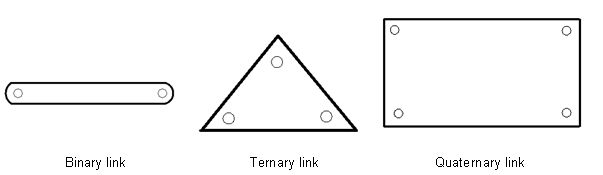
Fig.2.2 Types of links
The links can also be classified into Rigid, Flexible , Fluid according to its nature such as
Rigid link is the link which do not deform while transmitting the motion
Flexible link is the link which deform while transmitting the motion but does not affect its function of transmitting motion such as belts, chains etc.
Fluid link is the link which uses the fluid pressure to transmit the motion such as hydraulics jack, brakes and lifts.
2.2 RIGID BODY
A rigid body is a body in which the distance between the two points on the body remains constant or it does not deform under the action of applied force. In actual practice no body is perfectly rigid but we assume it to be rigid to simplify our analysis.
2.3 RESISITANT BODY
A Resistant body is a body which is not a rigid body but acts like a rigid body whiles its functioning in the machine. In actual practice, no body is the rigid body as there is always some kind of deformation while transmitting motion or force. So, the body should be resistant one to transmit motion or force.
Examples: The cycle chain is the resistant body as it acts like rigid body while transmitting motion to the rear wheel of the cycle, Belt in belt and pulley arrangement.
2.4 KINEMATIC PAIR OR PAIR
A kinematic pair is a connection between rigid bodies, which permits relative motion between them. When the links are supposed to be rigid in kinematics, then, there cannot be any change in the relative positions of any two chosen points on the selected link. In other words, the relative position of any two points does not change and it is treated as one link. Due to this rigidness, many complex shaped links can be replaced with simple schematic diagrams for the kinematic and synthesis analysis of mechanism.
2.4.1 CLASSIFICATION OF PAIRS
Kinematic pairs can be classified according to
a) Type of contact between elements
b) Type of relative motion
c) Nature of constraint or Type of closure
2.4.1 a) Type of contact between elements
Lower Pairs : A pair of links having surface or area contact between the members is known as a lower pair. The surfaces in contact of the two links are similar.
Examples: Nut turning on a screw, shaft rotating in a bearing, universal joint, etc.
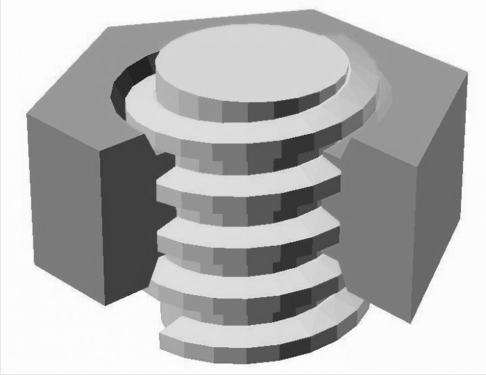
Fig. 2.3 Nut and screw (lower pair)
Higher Pair : When a pair has a point or line joint contact between the links, it is known as a higher pair. The contact surfaces of the two links are dissimilar.
Examples: Wheel rolling on a surface, cam and follower pair, tooth gears, ball and roller bearings, etc.
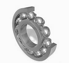
Fig. 2.4 ball and roller bearing (higher pair)
2.4.1 b) Type of relative motion
Sliding Pair : When two pairs have sliding motion relative to each other.
Examples: piston and cylinder, rectangular rod in rectangular hole.
Turning Pair : When one element revolves around another element it forms a turning pair.
Examples: shaft in bearing, rotating crank at crank pin.
Screw Pair : This is also known as helical pair. In this type of pair two mating elements have threads on it or its relative motion takes place along a helical curve.
Examples: Nut and screw pair as shown in figure 2.4, Screw jack
Rolling Pair : When one element is free to roll over the other one.
Examples: Ball and rolling as shown in figure 2.5, motion of wheel on flat surface
Spherical pair : When one element move relative to the other along a spherical surface.
Examples: Ball and socket joint
Explanation
In slider crank mechanism (Fig.2.6), crank (link 2) rotates relative to ground (link 1) and form a turning pair. Similarly, crank (link 2), connecting rod (link 3) and connecting rod (link 3), slider (link 4) also form turning pairs. Slider (link 4) reciprocates relative to ground (link 1) and form a sliding pair.
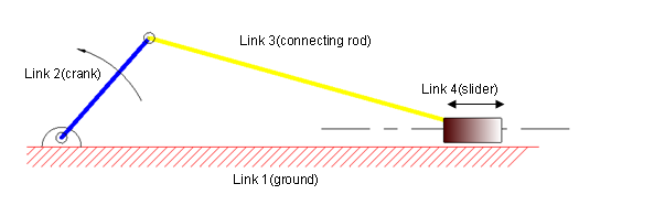
Fig.2.5 Slider crank mechanism
It should be noted here that the slider crank mechanism showed here is useful only in kinematic analysis and synthesis of the mechanism as actual physical appearance will be different and more complex than showed here. For designing the machine component the different approach will be followed.
2.4.1 c) Nature of Constraint or Type of closure
Closed pair : One element is completely surrounded by the other.
Examples: Nut and screw pair
Open Pair : When there is some external mean has been applied to prevent them from separation.
Examples: cam and follower pair
Last modified: Tuesday, 25 March 2014, 6:18 AM