

Site pages
Current course
Participants
General
MODULE 1.
MODULE 2.
MODULE 3.
MODULE 4.
MODULE 5.
MODULE 6.
MODULE 7.
MODULE 8.
MODULE 9.
MODULE 10.
LESSON 26 DESIGN OF POWER SCREWS
26.1 Materials
Screw is subjected to torque, axial compressive load and bending moment also, sometimes. Screws are generally made of C30 or C40 steel. As the failure of power screws may lead to serious accident, higher factor of safety of 3 to 5 is taken. Threads may fail due to shear, which can be avoided by using nut of sufficient height. Wear is another possible mode of thread failure as the threads of nut and bolt rub against each other. Nuts are made of softer material than screws so that if at all the failure takes place, nut fails and not the screw, which is the costlier member and is also difficult to replace. Plastic, bronze or copper alloys are used for manufacturing nuts. Plastic is used for low load applications and has good friction and wear properties. Bronze and copper alloys are used for high load applications.
26.1 Design of Screw and Nut
26.2.1 Compressive & Torsional Shear Stress in Screw Body
|
Figure 26.1 Screw and Nut |
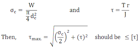
Screw body is subjected to axial compressive load, W and torque, T as shown in figure 26.1.
Direct Compressive Stress, 
Torsional Shear Stress, ![]()
where T = Applied Torque
J = Polar moment of inertia ![]()
r = ![]()
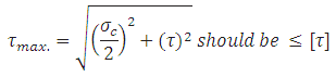
The principal shear stress is given by,
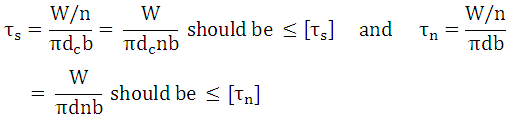
26.2.2 Shear Stress in Threads
The threads of the screw and nut are subjected to transverse shear forces due to the load W. Shear stress is maximum near the root diameter for the threads of the screw.
Maximum transverse shear stress in the threads of screw is given by,
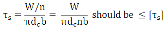
where, b – thread thickness at the core diameter
n - number of threads in engagement
In the threads of the nut, transverse shear stresses is maximum at the nominal diameter and is given by,

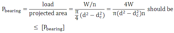
26.2.3 Bearing Pressure Between Surfaces of Screw and Nut
The bearing pressure between the contacting surfaces of the screw and nut is given by,

26.3 Design of Screw Jack
Screw Jack is a device, in which screw mechanism is used to raise or lower the load. Manually operated, portable type screw jack is the simplest and most commonly used. Its construction is shown in figure 26.2. In this, nut is fixed to the frame and remains stationary. When screw is rotated with the help of the handle, it moves axially. A cup is provided at the top to support the load. Cup remains stationary as the screw rotates and they rub against each. Applied torque has to overcome this friction also, which is known as collar friction. To avoid screw to completely turning out of the nut, washer is fixed on the lower end of the screw.
|
Figure 26.2 Screw Jack |
In order to design a screw jack for a load W, the following procedure may be adopted:
1. Calculate core diameter of the screw, considering only the compressive stress,
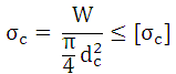
Value of core diameter should be standardized and corresponding values of mean diameter (dm) and outer diameter (d) should be taken.
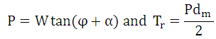
2. Calculate the effort at the handle and the torque required to lift load, W.
3. Calculate the direct compressive stress and torsional shear stress and find the principal shear stresses.
4. Find the height of nut (H), considering the bearing pressure on the nut.
Calculate the number of threads, n required for given allowable bearing pressure, by using equality sign in above relation.
Then, height of nut, H = number of threads X pitch = n p
5. Check the shear stress in the threads of screw and nut.
Note that allowable value of shear stress is different for screw and nut as different materials are used for them.
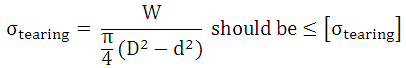
6. Find outer diameter (D) of the nut by considering its tearing failure.
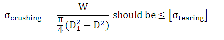
7. Find outer diameter of the nut collar (D1) considering crushing failure of the nut.
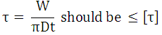
8. Find thickness of the nut collar (t) considering shear failure of the collar.
9. Assume outer and inner diameter of cup, coming in contact with the head as:
Outer Diameter, Do = 1.6 d
Inner Diameter, Di = 0.8 d
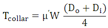
10. Calculate the torque required to overcome collar friction,
11. Total input torque required to lift load, W,
![]()
This is the total torque to be applied with the help of hand lever. Assuming that a force of 300 N (approximately) can be applied by hand. Required length of the handle is then given by, ![]()
12. Calculate diameter of the handle (dh) considering its bending failure.
![]()
where, Applied bending moment, M = P lh
Moment of inertia, I = ![]()
Distance of the farthest fiber from the neutral axis, ![]()
13. Take height of the head = 2 dh
14. Check the screw for buckling.
Effective or unsupported length of the screw is given by,
![]()
Critical Load is given by,
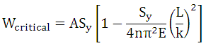
Where, Sy = Yield Strength of Screw Material
E = Modulus of Elasticity of Screw Material
n = End Fixity Coefficient = 0.25 (for one end fixed and load end free)
k = Radius of gyration = 0.25 dc
A = Cross-sectional Area of Screw
This critical load must be higher than the load for which the screw is designed.
15. Draw the sketch of the screw jack showing all its dimensions.
16. Find efficiency of the screw jack.
References
-
Design of Machine Elements by VB Bhandari
-
Analysis and Design of Machine Elements by V.K. Jadon
-
Machine Design by R.S. Khurmi
-
Design of Machine Elements by C.S. Sharma & K. Purohit
-
Mechanical Design by Peter Childs
Last modified: Monday, 24 March 2014, 5:10 AM