Site pages
Current course
Participants
General
MODULE 1.
MODULE 2.
MODULE 3.
MODULE 4.
MODULE 5.
MODULE 6.
MODULE 7.
MODULE 8.
MODULE 9.
MODULE 10.
LESSON 28 SELECTION OF ANTIFRICTION BEARINGS
28.1 Rated Life of a Bearing
Life of a bearing is the number of revolutions or number of hours at constant speed that the bearing runs, before the first evidence of fatigue crack in the balls or races. But test data shows large variation in the lives of identical bearings, operating under similar conditions. Because of this reason, life of bearings is expressed in terms of statistical average life of a group of bearings.
Rated life of a group of apparently identical bearings is defined as the number of revolutions that 90 % of bearings will complete or exceed before the first evidence of fatigue crack. It is also known as minimum life and L10 life.
Reliability is the ratio of number of bearings that complete L million revolutions to the total number of bearings tested. Therefore, by definition, rated life (L10) corresponds to 90% reliability of the bearing. Depending upon the type of application, bearings with reliability greater than 90% or less than 90% may also be required. Relation between bearing life and reliability is as follows:
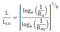
where, L10 = rated life of the bearing (life corresponding to 90% reliability)
L = life of the bearing corresponding to x % reliability
R90 = reliability of 90% (0.9)
Rx = reliability of x %
Using this relation, for given rated life of bearing, life of bearing corresponding to a reliability of x % (L) can be calculated.
28.2 Static Load Carrying Capacity
Static load carrying capacity (C0) of a bearing is defined as the static load corresponding to a total permanent deformation of balls and races, at the most heavily stressed point of contact, equal to 0.0001 of the ball diameter.
The bearing is subjected to some static load, when the shaft is stationary. This leads to plastic deformation in the balls and races. This deformation increases with increase in the static load. It has been established that a total permanent deformation of 0.0001 of ball diameter, at the most heavily stressed point of contact, can be tolerated without affecting operational properties of the bearing.
Different formulae have been developed for calculation of static load carrying capacity. However for selection of bearings, use of these formulae is not necessary; as the values of static load carrying capacity are directly given in manufacturer’s catalogue.
28.3 Dynamic Load Carrying Capacity
Dynamic load carrying capacity (C) is defined as the constant stationary radial load (in case of radial bearings) or constant axial load (in case of thrust bearings), which a group of apparently identical bearings, with stationary outer ring can endure for a rated life of one million revolutions with only 10 % failures.
Various relations have been developed for calculating dynamic load carrying capacity also, but again its value for different bearings is available in manufacturer’s catalogue. Table 28.1 gives basic dimensions and load capacities of different types of bearings.
28.4 Equivalent Bearing Load
In many applications, bearings are subjected to both radial and axial loads and are sometimes required to operate with stationary inner race and rotating outer race.
The equivalent dynamic load of a bearing is defined as the constant radial load in radial bearings or trust load in trust bearings, which if applied to the bearing, would give same life as attained by the bearing under actual conditions of loading. It is given by,
![]()
where, V = race rotation factor = 1 if inner race rotates
= 1.2 if outer race rotates
X = radial load factor
Y = thrust load factor
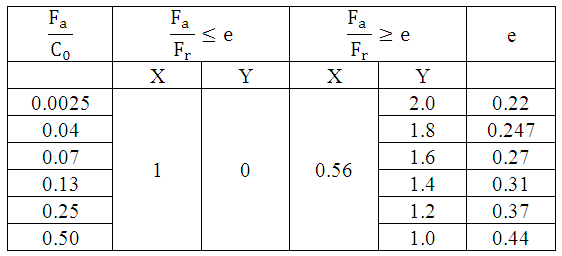
Values of X and Y are available in manufacturer’s catalogue. Table 28.2 gives values of X and Y for deep groove ball bearings.
Table 28.1 Dimensions & Load Carrying Capacities of Ball Bearings
|
Bearing No. |
Bore (mm) |
Outside Diameter (mm) |
Width (mm) |
Load Carrying Capacity (kN) |
|||||||
|
Single Row Deep Groove |
Single Row Angular Contact |
Double Row Angular Contact |
Self-aligning |
||||||||
|
C0 |
C |
C0 |
C |
C0 |
C |
C0 |
C |
||||
|
6200 6300 |
10 |
30 35 |
9 11 |
2.24 3.60 |
4 6.3 |
----- ----- |
----- ----- |
4.55 ----- |
7.35 ----- |
1.8 ----- |
5.7 ----- |
|
6201 6301 |
12 |
32 37 |
10 12 |
3.00 4.30 |
5.4 7.65 |
----- ----- |
----- ----- |
5.6 ----- |
8.3 ----- |
2 3 |
5.85 9.15 |
|
6202 6302 |
15 |
35 42 |
11 13 |
3.55 5.20 |
6.1 8.8 |
3.75 ----- |
6.30 ----- |
5.6 9.3 |
8.3 14 |
2.16 3.35 |
6 9.3 |
|
6203 6303 6403 |
17 |
40 47 62 |
12 14 17 |
4.40 6.30 11.00 |
7.5 10.6 18 |
4.75 7.2 ----- |
7.8 11.6 ----- |
8.15 12.9 ----- |
11.6 19.3 ----- |
2.8 4.15 ----- |
7.65 11.2 ----- |
|
6204 6304 6404 |
20 |
47 52 72 |
14 14 19 |
6.55 7.65 15.60 |
10 12.5 24 |
6.55 8.3 ----- |
10.4 13.7 ----- |
11 14 ----- |
16 19.3 ----- |
3.9 5.5 ------ |
9.8 14 ----- |
|
6205 6305 6405 |
25 |
52 62 80 |
15 17 21 |
7.10 10.40 19.00 |
11 16.6 28 |
7.8 12.5 ----- |
11.6 19.3 ----- |
13.7 20 ----- |
17.3 26.5 ----- |
4.25 7.65 ----- |
9.8 19 ----- |
|
6206 6306 6406 |
30 |
62 72 90 |
16 19 23 |
10.00 14.60 23.20 |
15.3 22 33.5 |
11.2 17 ----- |
16 24.5 ----- |
20.4 27.5 ----- |
25 35.5 ----- |
5.6 10.2 ----- |
12 24.5 ----- |
|
6207 6307 6407 |
35 |
72 80 100 |
17 21 25 |
13.70 17.60 30.50 |
20 26 43 |
15.3 20.4 ----- |
21.2 28.5 ----- |
28 36 ----- |
34 45 ----- |
8 13.2 ------ |
17 30.5 ----- |
|
6208 6308 6408 |
40 |
80 90 110 |
18 23 27 |
16 22 37.5 |
22.8 32 50 |
19 25.5 ----- |
25 35.5 ----- |
32.5 45.5 ----- |
39 55 ----- |
9.15 16 ----- |
17.6 35.5 ----- |
|
6209 6309 6409 |
45 |
85 100 120 |
19 25 29 |
18.3 30 44 |
25.5 41.5 60 |
21.6 34 ----- |
28 45.5 ----- |
37.5 56 ----- |
41.5 67 ----- |
10.2 19.6 ----- |
18 42.5 ----- |
|
6210 6310 6410 |
50 |
90 110 130 |
20 27 31 |
21.2 35.5 50 |
27.5 48 68 |
23.6 40.5 ----- |
29 53 ----- |
43 73.5 ----- |
47.5 81.5 ----- |
10.8 24 ----- |
18 50 ----- |
|
6211 6311 6411 |
55 |
100 120 140 |
21 29 33 |
26 42.5 60 |
34 56 78 |
30 47.5 ----- |
36.5 62 ----- |
49 80 ----- |
53 88 ----- |
12.7 28.5 ----- |
20.8 58.5 ----- |
|
6212 6312 6412 |
60 |
110 130 150 |
22 31 35 |
32 48 67 |
40.5 64 85 |
36.5 55 ----- |
44 71 ----- |
63 96.5 ----- |
65.5 102 ----- |
16 33.5 ----- |
26.5 68 ----- |
|
6213 6313 6413 |
65 |
120 140 160 |
23 33 37 |
35.5 55 76.5 |
44 72 93 |
43 63 ----- |
50 80 ----- |
69.5 112 ----- |
69.5 118 ----- |
20.4 39 ----- |
34 75 ----- |
|
6214 6314 6414 |
70 |
125 150 180 |
24 35 42 |
39 63 102 |
48 81.5 112 |
47.5 73.5 ----- |
54 90 ----- |
71 129 ----- |
69.5 137 ----- |
21.6 45 ----- |
34.5 85 ----- |
|
6215 6315 6415 |
75 |
130 160 190 |
25 37 45 |
42.5 72 110 |
52 90 120 |
50 81.5 ----- |
56 98 ----- |
80 140 ----- |
76.5 143 ----- |
22.4 52 ----- |
34.5 95 ----- |
|
6216 6316 6416 |
80 |
140 170 200 |
26 39 48 |
45.5 80 120 |
57 96.5 127 |
57 91.5 ----- |
63 106 ----- |
96.5 160 ------ |
93 163 ----- |
25 58.5 ----- |
38 106 ----- |
|
6217 6317 6417 |
85 |
150 180 210 |
28 41 52 |
55 88 132 |
65.5 104 134 |
65.5 102 ----- |
71 114 ----- |
100 180 ----- |
106 180 ----- |
30 62 ----- |
45.5 110 ----- |
|
6218 6318 6418 |
90 |
160 190 225 |
30 43 54 |
63 98 146 |
75 112 146 |
76.5 114 ----- |
83 122 ------ |
127 ----- ----- |
118 ----- ----- |
36 69.5 ----- |
55 118 ----- |
Table 28.2 Values of Radial Load Factor (X) and Thrust Load Factor (Y) for Deep Groove Ball Bearings
28.5 Load Life Relationship
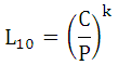
Relationship between bearing life, dynamic load carrying capacity and equivalent dynamic load, is given by,

where, L10 = rated bearing life
C = dynamic load carrying capacity
P = equivalent dynamic load
k = load life exponent = 3 for ball bearings
= 10/3 for roller bearings
|
Also,
|
|
where, L10h = rated bearing life in hours
N = speed of rotation in r.p.m.
28.6 Selection of Bearings
Following steps are generally followed in selection of antifriction bearings:
- Determine radial and axial forces (Fr and Fa respectively) acting on the shaft.
- Calculate the diameter of the shaft.
- Select suitable type of the bearing from manufacturer’s catalogue.
Following guidelines can be used for selecting ball bearings:
|
Type of Ball Bearing |
Fa/ Fr |
|
Single Row Deep Groove |
0.5 – 0.8 |
|
Double Row Deep Groove |
0.8 – 1.5 |
|
Angular Contact |
1.5 – 2.0 |
|
Self Aligned |
0.2 – 0.5 |
Select the lowest series of the selected category, depending upon the shaft diameter. Note the value of static load carrying capacity, C0. Refer table 28.1.
4. Select value of race rotation factor, V.
5. Determine values of radial and thrust load factors (X and Y) corresponding to the calculated values of Fa and Fr, and value of C0 of selected bearing. Refer table 28.2 for deep groove ball bearings.
6. Calculate equivalent dynamic load of the bearing,
![]()
7. Decide expected life of the bearing in millions of revolutions (L).
8. Calculate the required dynamic load carrying capacity for expected life, using load life relationship.
![]()
9.Dynamic load carrying capacity of the selected bearing should be greater than the required value calculated above, i.e.
![]()
If , choose higher series of the bearings from the catalogue and repeat the procedure from Step 3.
References
- Design of Machine Elements by VB Bhandari
- Analysis and Design of Machine Elements by V.K. Jadon
- Machine Design by R.S. Khurmi
- Design of Machine Elements by C.S. Sharma & K. Purohit
- 5. SKF General Catalogue
Last modified: Monday, 24 March 2014, 9:20 AM