Site pages
Current course
Participants
General
Module 1. Tractor Mechanics
Module 2. Traction
Module 3. Introduction to Transmission System
Module 4. Clutch System
Module 5. Gear Box
Module 6. Differential and Final drive
Module 7. Brakes
Module 8. Steering system
Module 9. Hydraulics
Module 10. Power Transmission
Module 11. Human Factors
Lesson 5. Tractor as a spring mass system
The Indian tractor is a frameless wheeled self propelled vehicle used as a source of power for operating mainly agricultural machinery, special equipment and towing trolleys. There is also no suspension system.
The suspension system is a set of devices that effect the undercarriage and the wheels. It is there to absorb the shocks from the field where the tractor is operating from reaching the operator.
The wheeled agricultural tractors are mounted on pneumatic rubber tyres. These air-filled tyres act as a system for absorbing the shocks. These act as spring-mass system having six degrees of freedom as shown in Fig. 5.1. The six degrees of freedom include vibration along the three principal axes, and can rotate about these three axes (longitudinal, vertical and transverse).
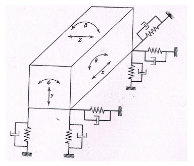
Fig 5.1
The motion terms generally related to the vehicles are: roll, pitch and yaw.
To vibrate or rotate along one of the three degrees of freedom, the tractor needs to be disturbed accordingly. Under normal conditions, the disturbances do not excite the tractor in the ‘x’, ‘β’ and ‘z’ directions.
The disturbances ‘Ф’ is called roll, ‘θ’ is called yaw and ‘y’ is called pitch.
A tractor as shown in Fig 5.2 can be represented as in Fig 5.3 as a system suspended on sprigs and dampers on the front and rear side. The displacement Xf and Xr at the front wheel and rear wheel respectively, causes the disturbance in the tractor. The various parameters associated with the analysis are as listed below:
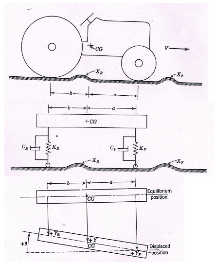
Fig 5.2
Fig 5.3
|
m |
Mass of the tractor |
|
Iθ |
Mass moment of inertia about transverse axis passing through the CG |
|
Y |
Vertical displacement of the CG due to the disturbance |
|
Yf |
Vertical displacement of front tyre |
|
Yr |
Vertical displacement of rear tyre |
|
Kf |
Spring constant of front tyre |
|
Kr |
Spring constant of rear tyre |
|
Cf |
Damping constant at front tyre |
|
Cr |
Damping constant at rear tyre |
|
a,b |
Describe the location of the CG |
|
wy |
Natural frequency along y coordinates |
|
wq |
Natural frequency along q coordinates |
From Fig. 5.3 the following relationships can be obtained:

The equation of motion in the y-direction is
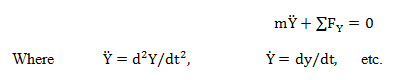
Or
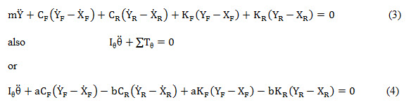
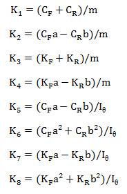
Substituting equations 1 and 2 into 3 and 4,
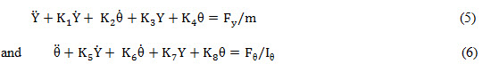
where
and FY and are linear combinations of ![]()
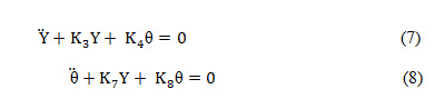
The undamped natural frequencies of this system can be determined by letting equations 5 and 6 be equal to zero (equilibrium condition), and by letting the damping equal zero or .
Hence,
In free vibration the natural modes will be:
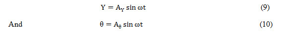
Where and are the amplitudes of free vibration.
If these values are substituted into 7 and 8, there results:
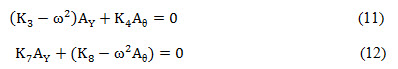
Since and are constants, they can be eliminated from equations 11 and 12 thus:
Therefore, the two natural undamped frequencies of this system are:
![]()
The frequencies previously determined do not consider viscous damping in the tires. The values determined are the result of either the front or the rear tires striking a bump to set the tractor in motion (vibrating) as it moves on a smooth surface.
Last modified: Saturday, 1 March 2014, 11:51 AM