Site pages
Current course
Participants
General
Module 1. Tractor Mechanics
Module 2. Traction
Module 3. Introduction to Transmission System
Module 4. Clutch System
Module 5. Gear Box
Module 6. Differential and Final drive
Module 7. Brakes
Module 8. Steering system
Module 9. Hydraulics
Module 10. Power Transmission
Module 11. Human Factors
Lesson 14. Working principle of speed reduction and torque transmission
Transmission System
While moving the vehicle/tractor in the field or for transportation purposes, there is a large variation of torque and speed requirements. The requirement of a transmission system are as listed below:
To reduce the rpm from the engine before it reaches the wheel.
To change the direction to rotation by providing a reverse gear.
To provide the required torque or speed depending on the field requirement or the operation being performed.
To provide a neutral position, where-in the power from the engine can be disconnected from the power train.
All these purposes are fulfilled using series of gears. There are various types of gears that are used for tractor and automotive applications. The Fig 14.1 shows the different types of gears used on tractors
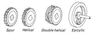
Fig 14.1 Types of Gears
Various types of gearing are used on a motor vehicle. The gearboxes employ one or more of the following:
1- Spur, teeth parallel to axis, used on sliding mesh.
2- Helical, teeth inclined to axis to form helix.
3- Double helical, two sets of opposing helical teeth.
4- Epicyclic or planetary, spur or helical gears rotating about centers which are not stationary.
Principle behind Gear Box
Consider following three cases in which there are a pair of gears in each case. The gear A is the driver and gear B is the driven.
In case I, the gear A (driver) is larger than gear B (driven), this case there is an increase in rpm of the driven as compared to the driver based on the following relation.
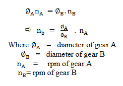
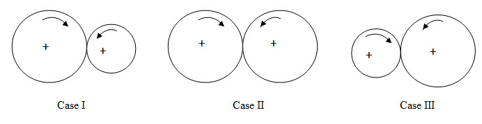
In case II, ØA is equal to ØB meaning that there is no change in the output speed as compared to the input speed.
In case III, ØA is smaller than ØB, leading to reduction of output rpm as compred to the input rpm.
Study of Torque output
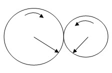
When the driver gear A drives the gear B with a torque, the torque exerted by gear A is given by
Where is radius of gear A.
F is the force that the gear A exerts.
Going back to the earlier figures the torque generated in gear B will be given by
![]()
In case of Case I,
TA> TB because rA > rB
In case II,
TA= TB (rA > rB)
In case III,
TA< TB because (rA < rB)
Therefore from the analysis of the three cases for both torque and speed, it can be stated that in a combination of gears where speed is increasing, torque reduces and vice-versa.
In case of automobiles, the starting torque is higher as compared to the cruising torque. The requirement of torque and speed keeps on changing with the driving conditions. In case of tractors this requirement and combination of speed and torque changes with the operation being performed. Providing for these requirements helps in running the engine and the machine for best tractor- machine system efficiency and returns the best fuel efficiency.
The speed ratios provided by tractor transmissions can be arbitrarily divided into low speed gears and transport gears. Low speed gears provide high torque at low speeds. These are required for performing operations such as tillage, crop planting and harvesting operations. The transport gears are used specifically for transportation purposes specially when there are good road conditions.
The gear box can also be classified based on arrangement of shafts between which the gears are mounted:
i) Parallel shafts (spur gears, helical gears, etc.)
ii) Shafts at an angle in the same plane (bevel gears)
iii) Shaft an angle not in the same plane (worm, hypoid gears)
Last modified: Monday, 3 March 2014, 5:39 AM