Site pages
Current course
Participants
General
Module 1. Tractor Mechanics
Module 2. Traction
Module 3. Introduction to Transmission System
Module 4. Clutch System
Module 5. Gear Box
Module 6. Differential and Final drive
Module 7. Brakes
Module 8. Steering system
Module 9. Hydraulics
Module 10. Power Transmission
Module 11. Human Factors
Lesson 27. HYDRAULIC SYSTEM
It is a mechanism in a tractor to raise, hold or lower of mounted or semi-mounted equipments by hydraulic means. All tractors are equipped with hydraulic control system for operating three-point hitch of the tractor.
Working principle: The working principle of hydraulic system is based on pascal's law. This law states that the pressure applied to an enclosed fluid is transmitted equally in all directions. Small force acting on small area can produce higher force on a surface of larger area
BASIC COMPONENTS OF HYDRAULIC SYSTEM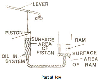
The basic components are:
(i) Hydraulic pump
(ii) Hydraulic cylinder and piston
(iii) Hydraulic tank
(iv) Control valve
(v) Safety valve
(vi) Hose pipe and fittings and
(vii) Lifting arms.
Operation: The hydraulic pump draws up oil from the oil reservoir and sends it to the control valve under high pressure. From the 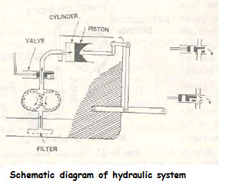 control valve, the oil goes to the hydraulic cylinder to operate the piston, which in turn, raises the lifting arms. The lifting arms are attached with implements. The hydraulic pump is operated by suitable gears, connected with engine.
There are two types of arrangements for storing hydraulic oil in the system:
(i) There is a common oil reservoir for hydraulic system and the transmission system in some tractors,
(ii) There is a special tank for hydraulic oil. It is separate from the transmission chamber.
Hydraulic pump: There are several types of hydraulic pump, such as gear pump, plunger pump, vane pump, and screw pump. Gear pump is widely used in tractors. Gear pump can flow a bigger amount of oil, compared to plunger pump. The oil pressure in the pump varies from 150 to 200 kg/cm2.Schema
Hydraulic cylinder: It is a bigger size cylinder, fitted with a piston and a connecting rod. It is also called ram cylinder. The connecting rod transmits power from the piston to the lifting arms. Piston moves in the hydraulic cylinder and causes reciprocating motion in the cylinder. The lifting arms are raised by the hydraulic pressure while raising the implement but it is lowered by its own weight.
Hydraulic tank: Hydraulic tank is used for storing hydraulic oil for the system. In some tractors, transmission chamber itself works as a hydraulic tank and same oil is used for transmission system as well as hydraulic system. In some tractors, separate tank is there for hydraulic oil.
Control valve: Control valve is a type of valve, which controls the movement of hydraulic oil to have desired direction, magnitude and speed of lifting. Thus the control valve is to perform three functions:
(1) to change the direction of lifting
(2) to change the power of lifting and
(3) to change the speed of lifting.
Oil filter: It is small filter, located at a convenient position in the passage of the oil.
TYPES OF HYDRAULIC SYSTEM
There are three important methods in hydraulic control system:
(i) Position control
(ii) Draft control
(iii) Mixed control.
Position control: In this system, constant depth of ploughing is maintained by automatic adjustment of draft of tractor. In this system the control valve can be operated directly by the driver to raise lower or hold an implement, mounted on the linkage at any chosen height.
Draft control: In this system, the working depth of any implement can be controlled continuously without the need for a depth wheel on the implement. The hydraulic control valve reacts to changes in the loading in either the top or lower links which arc due to changes in the draft or pull required by the implement. If any implement goes too deep its draft increases. This increase is sensed through the top link or lower links. The control system then raises the implement until the draft is back to the present level and the implement is at the original depth again using the draft control system.
HITCH AND CONTROL BOARD OF TRACTOR HITCH
For the efficient and safe tractor operation, implements are to be hitched properly.
Implements can be of Trailed, Semi-mounted and Mounted type.
Implements can be hitched in two ways:
(a) Drawbar hitch and
(b) Three point linkage.
Drawbar hitch: Drawbar is a device by which the pulling power of the tractor is transmitted to the trailing implements. It consists of a crossbar with suitable holes, attached to the lower hitch links. It is fitted at the rear part of the tractor.
Three-point linkage: It is a combination of three links, one is upper link and two are lower links, the links articulated to the tractor and the implements at their ends in order to connect the implement to the tractor.
Advantage of three-point linkage:
(1) Easy control of working implements
(2) Quick setting of implements
(3) Automatic hydraulic control of implements such as position control, draft control etc.
(4) Good balancing of attached implements.
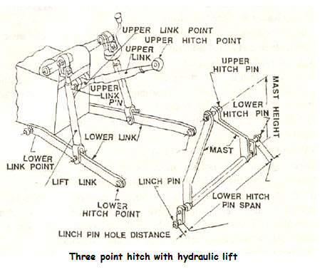
Implement control: The tractor with a built in lift system is connected to the implement through a specific type of mechanical linkage termed as three point linkage and the system is known as mounted system. The implement is connected to the tractor hydraulic system at two bottom links and one top link. Both the bottom links are connected to two lift arms through lift links. The lift arms are directly mounted on a rockshaft, which is further connected to the piston rod. Any movement of the piston is transferred to the bottom links. The top link is used for connecting the third hitch point of the implement and is adjustable for maintaining the implement level and suction angle. Load sensing for the draft control can also be done through the top link, which is spring, loaded. In some tractors the lower links are spring loaded for draft sensing. Depending upon the soil condition and type of operation, the mounted implement can be controlled either by position control or draft control.
Weight transfer: Rear part of the tractor is heavier than the front part to get higher tractive efficiency. However, sufficient weight on the front axle is also required to facilitate easy steering and to compensate the effect due to weight transfer. When the load is pulled, the tendency of front axle is to become light by losing some weight and the same adds to the rear axle. The higher the pull, the greater is the weight transfer. Mathematically this can be represented by:
![]()
where the line of pull is always assumed to be parallel to the ground.
Last modified: Monday, 3 March 2014, 6:53 AM