Site pages
Current course
Participants
General
Module 1. Hydraulic Basics
Module 2. Hydraulic Systems
MODULE 3.
MODULE 4.
MODULE 5.
MODULE 6.
MODULE 7.
MODULE 8.
LESSON 23. Hydraulic actuators and cylinders
Introduction
Hydraulic actuator are the devices which receives pressure energy and converts it to mechanical output in the form of force and motion. An actuator can be linear or rotary. A linear actuator gives force and motion outputs in a straight line. It is commonly known as a cylinder but is also referred to as a ram or linear motor. A rotary actuator produces torque and rotating motion. It is called a hydraulic motor or simply motor.
In the hydraulic systems pump is utilized to make the flow of the fluid and valves are utilized to the flow of fluid , pressure in the circuit or direction of flow. Whereas, the actual purpose is achieved with the help of actuators. The actuators are converting the hydraulic fluid energy into useful work or mechanical output. There are two basic types of hydraulic cylinders-
-
single-acting cylinder and
-
double-acting cylinder
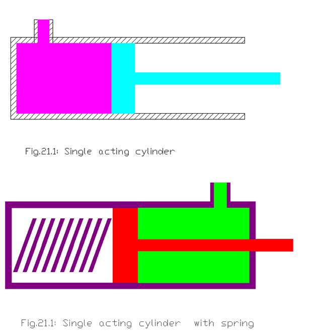
Single Acting cylinder
This type of cylinder is consists of a tube, sealed at both the ends and a piston along with piston rod which moves in the cylinder linearly in the tube. The fluid leakjage if any out of the cylinder is controlled by seals. When oil is pumped into the cylinder, it pushes the piston and the extend of piston takes place. To return or retract a cylinder, oil must be braught back to the reservoir.
In the single acting cylinder a piston returns either because of the weight of a load or from some mechanical force like a spring.
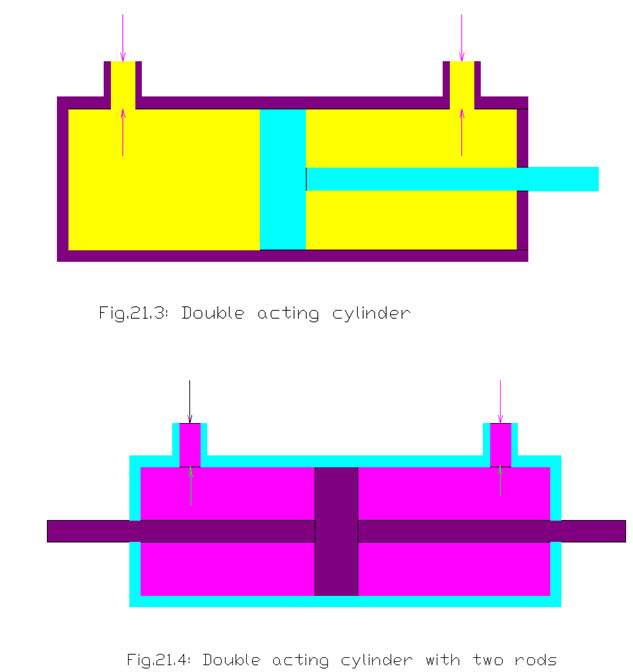
 Double Acting Cylinder
The double acting cylinder can hydraulically actuated or moved in both the directions with the help of fluid which is not in the single cylinder cylinders. As the oil is pumped into the head end of the piston it moves the piston to extend. The oil in the rod end is pushed out and returned to the reservoir. To retract a rod, flow is reversed. Hence oil from a pump goes into a rod end, and the oil from head end is connected to allow return flow.
Baics of cylinder actuator
Force
The hydraulic fluid pushes the piston and applies a force over it which can be given as
F = p x A
Where F = force, N
p = pressure, N/m2
A = correctional area, m2
It is assumed here that other side of piston is having negligible pressure.If pressure is acting on the rod side then it can be given as-
F = p x ( A- a)
a = rod area
Piston Speed
Piston speed is commonly based on the flow rate of fluid, hence at piston side
Q = A x v m3 / s
Q = flow rate, m3 / s
A = crossectional area, m2
v = velocity m/s
Flow rate at rod end Q = (A – a) x v m3 / s
Piston power
It can be defined as the product of force and velocity, which can be given as-
P = F x v watts
Where F = force, N
v = velocity, m / s
Example :
A single acting cylinder has piston diameter of 70 mm and is having a fluid flow rate of
0.2 x 10 -3m3/s , with applied pressure of 1.5 x 10⁶ N/m2calculate the followings
a) thrust force
b) velocity
c) power
Soln:
Given D = 70 mm
Q = 0.2 x 10 -3m3/s
p = 1.5 x 10⁶ N/m2
0.07
A = \[\frac{{\pi {D^2}}}{4}\]
= \[\frac{{\pi {{\left( {0.07} \right)}^2}}}{4}\]
= 0.0038 m2
F = p x A
= 1.5 x 106 x 0.0038
= 5772.6 N
= 5.77 kN
Q = A x v m3 / s
0.20 x 10 -3 = 0.0038 x v
v = \[\frac{{0.20{\text{x}}10{\text{}} - 3}}{{0.0038}}\]
= 0.0526 m/s
P = F x v
= 5772.6 x 0.0526
= 303.8 watts
Example 2 :
In a double acting hydraulic cylinder the push force produced is 12.1 kN with available flow rate at both the directions of 0.2 x10⁻³ m3/s . The bore of the cylinder is 98 mm with stroke of 125 mm. and the rod diameter is 40 mm. Calculate the followings-
a) pressure of the system
b) force required to pull
c) speed in outward stroke
d) Speed in inward stroke
e) power in inward stroke
Soln. :
Given F = 12.1 kN
= 12100 N
Q = 0.2 x10⁻³ m3/s
D = 98 mm
= 0.098m
A = \[\frac{{\pi {D^2}}}{4}\]
= \[\frac{{\pi {{\left( {0.098} \right)}^2}}}{4}\]
= 0.0075 m2
L = 125 mm
d = 40mm
= 0.04 m
a = \[\frac{{\pi {D^2}}}{4}\]
= \[\frac{{\pi {{\left( {0.04} \right)}^2}}}{4}\]
= 0.0012 m2
Pressure p = F/A
= \[\frac{{12100}}{{0.0075}}\]
= 1.61 x 10⁶ N/m2
Pulling force F = p ( A – a)
= 1.61x10⁶ (0.0075 – 0.0012)
= 10164 N
speed in outward stroke = Q/A
= \[\frac{{0.2x10 - 3}}{{0.0075}}\]
= 0.0266 m/s
speed in outward stroke = Q/ (A – a )
= \[\frac{{0.2x10 - 3}}{{\left( {0.0075 - 0.0012} \right)}}\]
= 0.031 m/s
Power P = pxQ
= 1.61x106x0.2x10-3
= 322 N
Last modified: Tuesday, 18 March 2014, 5:56 AM