Site pages
Current course
Participants
General
Module 1. Hydraulic Basics
Module 2. Hydraulic Systems
MODULE 3.
MODULE 4.
MODULE 5.
MODULE 6.
MODULE 7.
MODULE 8.
Lesson No 32 Robotics , Hydraulic and Pneumatics and Programmable Logic Control
Introduction
Robots are making a considerable impact on the many aspects of modern life, from industrial field to transportation, and in agricultural fields. It is basically a machine which is skilled and having intelligence (computer).. Production, assembly and packaging fields are are specifically automated. The development of automation pushed forward for development of robots . Hydraulic and pneumatic drive are widely used to give linear or rotary outputs in the robos. Therefore, these systems use devices such as linear pistons and rotary vane actuators to accomplish the motion of the joint. Pneumatic drive is normally used for smaller robots used in simple material transfer applications. Electric drive and hydraulic drives are used on sophisticated industrial robots. Control engineering and automation has evolved long back. Earlier to which human beings were the main source controlling systems. The development of low cost computer has revolutionized the in the field of programmable logic controller (PLC). These are gaining popularity in many applications, specifically in manufacturing controls, etc.
Robotics
Robotics may be defined as the technology which deals with the design, manufacturing operation and application of robots along with computer systems for the control, sensory feedback, and information processing. Robots are normally consisted of several systems working together as a whole. Generally these are comprised of following systems-
Controller
Body
Mobility
Power
Sensors
Tools
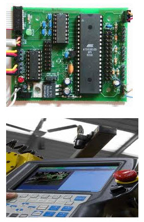
Control System
The controller controls the movements of the robot which is also called brain or intelligence of the robot. It generally uses a computer which stores the information about the robot and the work environment and it also execute programs which operate the robot. The control system contains programs, data algorithms, logic analysis and various other processing activities which enable the robot to perform. Depending upon the task to be performed by robots its control system may be of simple type or sophisticated type. It is having a Central processing Unit (CPU) and Power Unit which enable it for power generation, power conditioning, power distribution and control, analog and digital input output (I/O) control and processing, computing , and data storage in memory, etc.
Body
The body of the robot may be of any shape or size depending upon type of task to be performed by it. Industrial robots are generally of the shape of a body less arm as it is suitable to the job to be performed by it . Space robots have many different body shapes such as a sphere, a platform with wheels or legs depending upon task to be performed . Some planetary rovers have solar platforms driven by wheels. Aerobat bodies are balloons that will float through the atmosphere of other worlds collecting data.
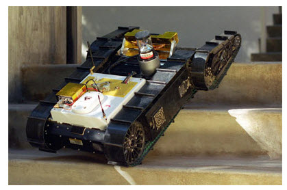
Mobility
Mobility of robot is basically movement of it viz how do robots moves. It depends on the task to be performed under a particular environment. http://web.mit.edu/afs/athena/org/t/towtank/www/tuna/pictures.html Unmanned submersible robots are used ocean studies or industry for which automated underwater vehicles use propellers and rudders to control their direction of travel. Their shape may also be similar to fish for easy mobility. Similarly land based robots or rovers may move on legs or tracks or wheels. If the surface uneven the robots can move easily with the track type of arrangement.
Power
Robots can be powered with electric, pneumatic or hydraulic source. Electric motors are efficient, require little maintenance, and are less noisy. Pneumatic robots use compressed air and come in a wide variety of http://jewel.morgan.edu/~salimian/courses/IEGR470/223_lab.htmlsizes. It requires another source of energy like electricity or gasoline to provide the compressed air. Hydraulic robots use oil under pressure and generally perform heavy duty tasks. This is larger and heavier than the other power sources. A hydraulic robot also needs another source of energy to move the fluids through its components. Pneumatic and hydraulic robots require maintenance of various components like tubes, fittings and hoses which connect the various components.
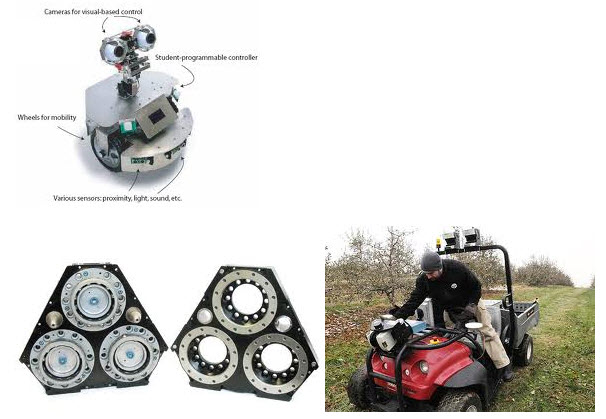
Sensors
Sensors in the robot are the devices which collect the useful information as a engineering parameter about the internal state of robots. These are used to communicate with outer world. These also measure physical quantities like contact, distance, light, sound, strain, rotation, magnetism, smell, temperature, inclination, pressure , etc. Sensors generate the signals which subsequently processed with the help of computer brain of robot to provide meaningful information. Robots are equipped with sensors and hence they can have an understanding of their surrounding environment and make changes in their response on the basis of collected information. Robot can also be fitted with acoustic sensor to detect sound, motion or location, infrared sensors to detect heat sources, contact sensors, tactile sensors to give a sense of touch.
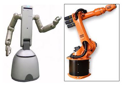
Tools
Robots are fitted with tools called end effectors so as to interact with the environment and to carry out assigned tasks. These tools will have the variation according to the tasks to be performed for which it has been designed. A robot in the manufacturing unit will be fitted with interchangeable tools such as paint sprayers or welding torches. Many robots carry their tools at the end of a manipulator. The manipulator contains a series of segments for moving objects. The manipulator includes the arm, wrist and end effectors. An end effector is a tool or gripping mechanism attached to the end of a robot arm to accomplish some task like a gripping device, a paint gun, a drill, an arc welding device, etc. There are specific tools to do a particular
Programmable Logic Controller (PLC)
A programmable logical controller (PLC) is a digital computer which is used in automation for processes, such as control of machinery in a factory assembly line, production, pneumatic , hydraulic ,etc.. PLCs are used in many industries and variety of machines. PLC basically used to monitor inputs, and depending upon their state make decisions by using its program or logic, to control its outputs to automate a machine or a process. The PLC may be designed for multiple inputs and output arrangements. Programmable Logic Controllers (PLCs) are microprocessor-based devices used to control industrial processes or machines. They provide advanced functions, including analog monitoring, control and high speed motion control as well as share data over communication networks.
Advantages
It is rugged in design
It can withstand vibrations, temperature, humidity, and noise.
It is provided with interfacing for inputs and outputs
It can be easily programmed
The language used for programming is simple
Cheap and reliable
Low cost
Disadvantages
Connecting wires is difficult
It is difficulty to make changes or replacements.
It is difficulty to find errors
Configuration of PLC
PLC is basically an industrial microcontroller system or microprocessor based system which is having hardware and software as per the requirement or use. Block diagram below give the details of various components of it.
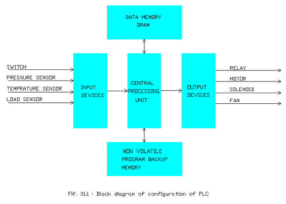
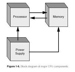
Central Processing Unit ( CPU)
Central Processing Unit is the brain of a PLC controller. CPU itself is usually one of the microcontrollers. These are normally 16 and 32 bit microcontrollers. The CPU consists of a microprocessor, memory chip and other integrated circuits to control logic, monitoring and communications. It can operate in different operating modes. In programming mode it accepts the downloaded logic and then in run mode it can execute the program and operate the process.
CPU also takes care of communication, interconnecting of other parts of PLC controller, program execution, memory operation, overseeing input and setting up of an output.
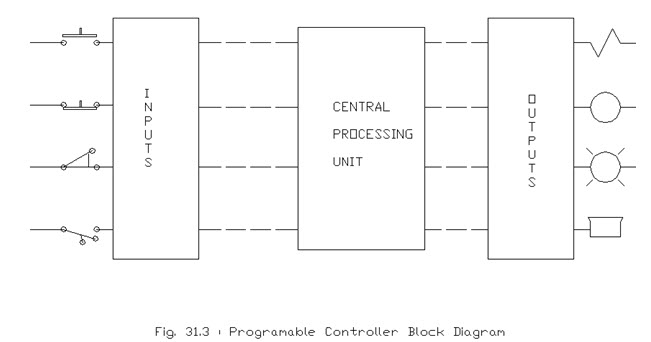
Input Output System
The input output (I/O) system provides the physical connection between the equipment and the PLC. A PLC input device is anything which gives an input to the PLC. These can consist of digital, analog, switches, sensors, intelligent devices etc. A digital input card in an input device handles discrete devices which give a signal like on or off such as a pushbutton, limit switch, sensors or selector switches. An analog input card converts a voltage or current into a digital form which is an equivalent number easily accepted by the CPU. Force transducer, pressure transducer, thermocouples, torque sensors etc are give the analog signals which are converted into digital form and processed by microprocessors. Similarly output device is also consist of digital or analog types. A digital output card gives the signal out to put a device on or off like as lights, LEDs, small motors, and relays, etc. An analog output card will convert a digital number sent by the CPU to real world voltage or current which are used to drive mass flow controllers, pressure regulators and position controls or some other device.
Programming PLC
The software part is the heart of a PLC and is written by a programmer. The programming is so done that the PLC can control or monitor the devices. These softwares are executed by the processor in the CPU module or controller module. There are various types of PLC software design packages which are in use. The logic can be written in Ladder Logic, Instruction List, Sequential Function Charts, or any of the IEC (international electrotechnical commission ) languages.
Power Supply
In PLCs electrical power supply is used to operate the central processing unit. Most PLC controllers work on DC voltage. Therefore it is necessary to convert the 230 V AC voltage to required DC voltage needed for logic circuit of processor and also for I/O system of controller. The power supply may be a separate module in the PLC or some times integral part of the CPU. . Depending upon the design of PLC current rating will be by the power supply to the I/O module . Different types of modules use different amounts of electrical current. This electrical supply is usually not used to start external inputs or outputs. Separate supplies are provided in starting PLC controller inputs or outputs. By doing so pure supply is applied to the CPU which is not affected by industrial environment.
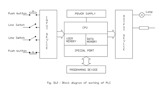
Working of PLC
A PLC interfaces various types of external electrical and electronic signals. These signals can be AC or DC currents or voltages from various sensors or devices. It ranges 4 to 20 milli- amperes (mA) or 0 to 120 VAC and 0 to 48 VDC. These signals are called as I/O points.The I/O ( input/output) system is physically connected to the field devices which are used in the control of a process. These field devices may be discrete or analog I/O devices, like load cells, pressure transducers, push buttons, motor starters, solenoids, limit switches, etc. The I/O interfaces provide the connection between the CPU and the information providers (inputs) and controllable devices (outputs). The CPU completes three processes viz. it reads, the input data from the field devices via the input interfaces, then it executes, the control program stored in the memory system, and thirdly it writes, or updates, the output devices though the output interfaces. This process of sequentially reading the inputs, executing the program in memory, and updating the outputs is known as scanning.
Last modified: Thursday, 27 March 2014, 10:57 AM