Site pages
Current course
Participants
General
Module 1. Introduction to by-products and waste ge...
Module 2. Waste management concepts
Module 3. Direct combustion of solid waste
Module 4. Thermo-chemical conversion of solid waste
Module 5. Bio-chemical conversion of solid waste
Module 6. Solid waste management
Module 7. Effluent treatment and disposal
Module 8. Presence of typical chemicals
Topic 9
Topic 10
Lesson 5.
Biomass is any material produced through Carbon Dioxide fixation due to photosynthesis reaction in presence of sun light. In this process the sun energy is converted to carbohydrates stored in the plants as chemical energy. Wood and agricultural crop residues are some important biomass renewable energy sources. The biodegradable component of the Municipal Solid Waste, animal wastes and commercial and industrial wastes are also other significant biomass as renewable energy sources.
Biomass materials can be converted to other useful products through thermo-chemical, biological, chemical and mechanical conversion processes. The key difference in thermo-chemical and biological conversion processes is that the biological conversion is relatively slow process typically taking hours, day and weeks (anaerobic digestion, fermentation) or years (landfill gas by digestion) for reaction to be completed. Thermo-chemical conversion process gives multiple and complex products and takes place in short reaction time.
Biomass gasification
Gasification processes convert biomass into combustible gases that ideally contain all the energy originally present in the biomass. In practice, gasification can convert 60% to 90% of the energy in the biomass into energy in the gas. Gasification processes can be either direct (using air or oxygen) or indirect (transferring heat to the reactor from the outside). The gas can be burned to produce industrial heat, to run engines for mechanical or electrical power, or to make synthetic fuels.
Biomass gasification is already a well proven technology. Approximately one million downdraft gasifiers were used to operate cars, trucks, boats, trains, and electric generators in Europe during World War II. Development of biomass gasification was disrupted in 1946 as the war ended and inexpensive (15¢/gal) gasoline became available. The magnitude of damage inflicted on gasifier technology by this disruption can be seen by the fact that it is difficult for even the "advanced" technology of the 1980s to achieve on tests what was routine operation in the 1940s. The design, research, and manufacturing teams of that decade have all disbanded. We have from the past only that small fraction of knowledge that has been published, whereas the large bulk of firsthand experience in operation design has been lost and forgotten.
Gasification was rediscovered in an era of fuel shortages and higher oil prices, and there are gasifier engine projects under way in more than 20 countries for producing process heat and electrical and mechanical power. In its rebirth, however, the existing technology has uncovered major problems in connection with gasification reactor scaling factors, effluent and gas cleanup and the fuel supply, which were less important during the emergency of World War II. Today, these problems must be solved if biomass gasification is to reemerge as a fuel source.
Gasification process mechanism
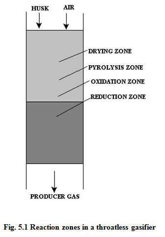
Different processes and operations occurring in the gasifier reactor are mainly in four reaction zones (i.e., oxidation, reduction, pyrolysis and drying). The sequence of reaction zones in a gasifier depends on the type of gasifier and direction of flow of fuel and air or gas. In the oxidation zone, carbon and hydrogen of the biomass are oxidized to carbon dioxide and water vapor in accordance with the following reactions.
C + O2 --------------> CO2 + 393.8 MJ kg-mol-1 (1)
H2 + 1/2 O2 ----------> H2O (l) + 286.1 MJ kg-mol-1 (2a)
H2 + 1/2 O2 -----------> H2O (g) + 241.5 MJ kg-mol-1 (2b)
Reactions 1 and 2a & 2b are the principal oxidation reactions. They are highly exothermic. Almost all the oxygen consumed in gasification process is used up in the oxidation zone. The temperature in the oxidation zone range from 800 to 1200 °C, depending upon the type of the gasifier and fuel. Carbon dioxide and water vapor leave oxidation zone at high temperature and move into reduction zone.
In reduction zone, carbon dioxide and water vapors are reduced to carbon monoxide, hydrogen and methane in accordance with the following reactions.
Water gas reaction:
H2O + C ----------> CO + H2 - 122.6 MJ kg-mol-1 (3)
Boudauard reaction:
CO2 + C -------------> 2CO - 172.6 MJ kg-mol-1 (4)
Water gas shift reaction:
CO2 + H2 -------------> CO + HO - 41.2 MJ kg-mol-1 (5)
Methane formation reaction:
C + 2H2 ---------------> CH4 + 75.0 MJ kg-mol-1 (6)
Reactions 3 to 6 are the principle reduction reactions and are reversible. For reaction 3 the equilibrium temperature is about 900 °C. The equilibrium temperature for reaction 4 is about 1100 oC. Optimum temperature for reactions 5 and 6 is 700 to 600 °C. It indicates that the higher reactor temperature during gasification process favors higher concentration of CO and H2 in the producer gas. The low reactor temperature leads to higher methane concentration in producer gas.
Major reduction reactions (i.e., reactions 3, 4 and 5) are endothermic. Heat liberated in the oxidation zone of the gasifier is used for reduction reactions. The gas temperature drops from around 1000 °C in the oxidation zone to 450 °C at the end of the reduction zone.
Apart from the oxidation and reduction reactions, pyrolysis and drying also takes place in gasifiers. Pyrolysis takes place adjacent to the oxidation or reduction zones depending upon the type of gasifier in a temperature range of 200 to 500 °C.
Type of gasifier reactors
The gasifiers are usually classified on the basis of direction of fuel and air or gas flow in the reactor. The classification of gasification reactors often referred in the literature is given below:
Up draft
Down draft
Fluidized bed
Circulating fluidized bed
Entrained flow
Up draft gasifier
An up draft gasifier is characterised by a counter current flow of the fuel and air or gas in the reactor. Fuel is fed from the top and air is introduced at the bottom of the reactor. The producer gas exits from the top of the gasifier. Oxidation zone is formed at the bottom of the gasifier. The reduction, pyrolysis and drying zones are formed above the oxidation zone in sequence.
In an up draft gasifier, the producer gas passes through the low temperature pyrolysis and drying zone in the gasifier before exit. The tar released in pyrolysis zone and water vapours formed in drying zone move along with the producer gas unconverted. Thus the gas generated from an up draft gasifier contains high quantity of tar and moisture. The tar content of the producer gas varies from 1 to even 20 g/Nm3. The gas is therefore considered suitable for thermal applications where removal of tar is not very essential. Up draft gasifiers generally, operate at high efficiency (hot gas basis) because of low gas temperature at the gasifier exit. Current R & D work in the country on up draft gasifiers, is mainly for thermal applications.
Down draft gasifier
Down draft gasifiers are characterized by co-current flow of air or gas and the fuel. In a dawn draft gasifier, normally fuel is introduced from the top while air is fed either from the top of the reactor or from the side, in the oxidation zone.
In a down draft gasifier, the pyrolysis products (i.e., tar and other condensable components) pass through high temperature oxidation and reduction zones. This is why, most of the tar is either burned or cracked thermally in the gasifier itself. The producer gas generated from a down draft gasifier has minimum quantity of tars and other condensable and is considered the best for engine operation. Down draft gasifiers can be further classified as down draft gasifier with throat and constant diameter throatless gasifier.
Down draft gasifier with throat
This gasifier has a narrow section below the air entrance point in the reactor which is called throat. Due to decrease in the cross-sectional area at the throat, the air or gas velocity increases resulting high and better temperature distribution in the oxidation zone.
In a down draft gasifier, pyrolysis zone is formed above the oxidation zone, whereas the reduction zone is formed below the oxidation zone.
This type of gasifier is highly fuel specific and operates only on wood chips, charcoal and selected woody agricultural crop residues. Its cold gas efficiency is about 75% at full load operation. These gasifiers are available in the capacity range of 2.5 to 250 kW.
Throatless gasifier
Down draft gasifier with throat produces best quality producer gas, but it is not suitable for gasification of paddy husk. Since paddy husk is an important agricultural crop residue having potential as an energy source, a throatless down draft gasifier was conceived for gasification of paddy husk. The reactor has a constant diameter without throat. The reaction zones sequence in this gasifier is similar to that of the down draft gasifier with throat. The reaction zones in a batch operated throatless gasifier are shown in Fig.5.1.
In batch operation, the residue/ash left after the gasification accumulates in the gasifier. The reaction zones thus keep on moving up in a throatless gasifier. However, in a continuous reactor where ash removal and material feeding are continuous, the reaction zones remain more or less at the same location. The cold gas efficiency of this gasifier varies from 55 to 65% depending upon the operating conditions. Throatless gasifier has been successfully operated using low density leafy biomass, for engine quality gas production.
Simple design, operation and maintenance of a batch operated throatless gasifier supports its use in remote village environment where high level technical skill and workshop facilities are not available. The gasifier can be used to run IC engine (5 to 20 hp) for farm irrigation or water pumping.
Fluidized bed gasifier
Fluidized bed gasifier is a homogeneous reactor bed of inert sand material. Usually high alumina refractory sand is used as a bed material and fluidization is carried using air/gas. Usually ground or palletized biomass having uniform size is used in these gasifiers. The fuel is introduced in the inert bed material. Air is introduced through an air distributor at the bottom of the bed in the reactor. Oxidation, reduction pyrolysis processes occurs simultaneously. These gasifiers are available in higher capacity ranges (1 to 5 MWe). The diameter of fluidized bed reactor may be selected in such a way that at maximum load the gas velocity is less than the terminal velocity of the bed smallest particle to avoid the carryover of the excess solid particles. At lower loads the velocity should be more than the largest particle otherwise the bed may get de-fluidized.
In fluidized bed gasifier a precise control of reactor temperature can be maintained at a desired level by adjusting air fuel ratio. So materials with high ash and low ash slagging temperature can also be gasified in a fluidized bed gasifier. As a matter of fact any type of fuel can be used in this type of gasifier provided that the material is of uniform and small size. This gasifier is characterized by high gas exit temperature, very high solid particulate matter in the gas and relatively low efficiency. The producer gas generated from a fluidized bed gasifier requires extensive cleaning for thermal as well as mechanical applications.
Circulating fluidized bed reactor
In a circulating fluidized bed reactor the diameter is reduced to increase the gas velocity above the terminal velocity of the smallest particle in the bed. Therefore, all the solids are taken out of the reactor along with the gas and captured in a cyclone. The solid particles from the down comer of the cyclone are re-circulated back to the reactor with a small purge of fresh air.
Utilization of producer gas
The producer gas is a mixture of Carbon dioxide, Hydrogen and Methane as combustible gas along with Nitrogen and Carbon dioxide. Typical producer gas characteristics are given in table 1. The gas has a heating value of 4.5 to 6 MJ/Nm3 and can give a self sustaining flame on ignition. The gas can thus be used for various thermal applications such as boiler fuel and process heat energy in small/medium industries, cooking, welding etc. The gas can also be used a a supplementary fuel in an unaltered diesel engine and it can operate a spark ignition engine to produce mechanical power, which can be converted to electricity. In the following two case studies are indicated showing the electricity generation from a throateless rice husk operated gasifier and thermal application of gas from a down draft gasifier with throat. There gasifiers were developed and tested in the School of energy Studies for Agriculture, PAU, Ludhiana.
Producer gas composition:
Carbon Monoxide 20-22%
Hydrogen 12-18%
Methane 2-3 %
Carbon dioxide 8-12%
Nitrogen 45-55%
Oxygen > 1%
Others Tar, SPM,
Lower heating value of gas 4 to 5.5 MJ/Nm3
Throatless gasifier
The gasifier had capacity to generate gas for a 10 kW capacity diesel engine generator set. A schematic diagram of 10 kW gasifier engine system is shown in Fig.5.2.
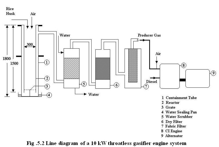
The gasifier engine generator set was operated for 250 hours. On the basis of the operating experiences the performance evaluation of a 10 kW throatless gasifier engine is:
Capacity 10 kW
Gasifier efficiency 65%
Gas production rate 20 m3/h
Rice husk consumption 1.4 kg/kWh
Engine speed 1500 rpm
Diesel replacement 72%
Engine efficiency 26%
Exhaust gas temp. 450 oC
Down draft gasifier with throat
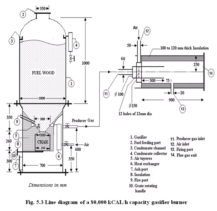
Down draft gasifier with throat of different capacities ranging from 2.5 to 100 kW have been designed and developed in the School of Energy Studies for Agriculture, PAU, Ludhiana. The producer gas has been used for running un-altered diesel engines in dual fuel mode (producer gas and diesel) replacing about 70% diesel by producer gas. The gasifier have also been used for thermal applications in small industries replacing their oil/coal/wood fired furnaces. A schematic diagram of 20 kW gasifier gas burner system is shown in Figure.
Most of the biomass materials (crop residues, fuel wood species, agro-industrial residues etc) can be converted to producer gas via thermo-chemical conversion route by selecting appropriate type of gasification system. The producer gas is a low calorific value combustible gaseous fuel and can be used for thermal applications in industries. The gas can replace the liquid fuel in internal combustion engines i.e. partial replacement in an unaltered CI engine and total replacement in a SI engine.
Performance evaluation of a 80,000 kCal/h gasifier
|
Parameter |
Value |
|
Rated capacity |
80,000 kCal/h or 20 kWe (approximately) |
Biomass Feed Stock |
|
|
Name |
Eucalyptus/any woody biomass |
|
Size |
30-45 mm |
Moisture |
8-12% |
Consumption |
22-24 kg/h |
Producer Gas Flow rate |
65 m3/h at NTP
|
|
Average gas composition (Vol.) |
|
Hydrogen |
14.38 |
|
Carbon monoxide |
19.65 |
|
Carbon dioxide |
9.32 |
|
Methane |
1.98 |
|
Oxygen |
2.72 |
Nitrogen |
51.95 |
|
Heating Value of Producer Gas |
1220 kCal/m3 |
|
Producer gas temperature |
250-400 OC |
|
Gasifier efficiency (hot gas) |
81.4% |
Last modified: Wednesday, 29 January 2014, 9:34 AM