Site pages
Current course
Participants
General
Module 1. Dairy Development in India
Module 2. Engineering, thermal and chemical proper...
Module 3. Unit operation of various dairy and food...
Module 4. Working principles of equipment for rece...
Module 5. Dairy plant design and layout, compositi...
Module 6. Deterioration in products and their cont...
Module 7. Physical, chemical and biological method...
Module 8. Changes undergone by the food components...
Module 9. Plant utilities requirement.
References
Lesson10. Milk Reception and Homogenization
10.1 Milk Reception
Milk may be received at the dairy plants for processing either in cans direct from producers or in tanks from a milk chilling centres. The first stage of the process of reception involves emptying the cans over the tip-tank or weigh-tank, if milk is received in cans. This process may be carried out entirely by hand, by a mechanical inverter, or by a "hand-assisted" method. Drainage of the can is important and it is generally considered that for cans of 40 ℓ capacity, a drainage time of at least 30 seconds should be allowed.
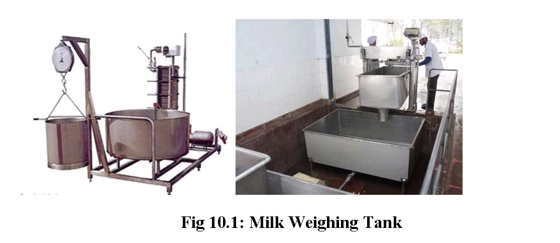 Where weigh-tanks are installed, after the weight of the consignment has been recorded, the contents are discharged into a tank immediately below it from which the milk is pumped through a cooler to a storage tank. Where milk is measured volumetrically, the cans are tipped directly into the tip-tank, from which milk is pumped to the cooler. Where a higher throughput is required, the procedure must be mechanized.
Most raw milk is nowadays delivered to the dairy plant through milk transport tankers, either trucks or trailers varying from approximately 7,500 to 25,000 ℓ in capacity. The receiving operation is divided into three phases: (a) preparing to unload (b) unloading and (c) weighing.
Preparing to unload normally involves agitating the milk. Inspecting for off-flavors (generally odours) and connecting the unloading hose to the tanker outlet. Sampling is always preceded by agitation.
The product is then transferred from the tanker to a receiving or storage tank with the help of a centrifugal or rotary pump. The receiving tanks may be mounted on scales or load cells to permit full tank loads to be weighed. Alternatively, the milk may be pumped through a meter for volumetric measurement. Modern dairy plants use air-operated valves to control flow in the receiving operation and CIP system for tankers, tanks and pipelines.
Most plants make at least spot checks of the incoming product volume using the following methods: (a) weighing or measuring the tankers, (b) weighing in receiving or storage tanks, (c) metering and (d) liquid-level measurement in the storage tank.
The milk that comes directly from the farmers is paid on the basis of measurement in the farm bulk tank, using a graduated dip stick. The use of receiving tanks on scales or load cells adds extra equipment and accordingly, capital and operating costs. Two receiving tanks are required for an efficient operation so that one can be filled as the other is emptying.
In the weighing-tank method, the milk is pumped from the tanker into a special weighing tank, with load cells built into the feet. The cells supply an electric signal that is always proportional to the weight of the tank. The weight of the contents in the tank can be recorded when all the milk has been delivered. After this, the milk is pumped to a silo/storage tank. This system is subject to wind load errors and is thus limited to enclosed tanks. Milk in the storage tank may also be measured with a liquid-level gauge. Maximum accuracy of gauges of this type has been reported under field conditions, but more recent applications combining silo-type tanks, diaphragm-type pressure sensors and multi-range manometers provide improved performance.
Sanitary meters are used in a number of plants. Measurement is by determining volumetric displacement, mass flow rate or velocity. Variations in air content, temperature, flow rate, back pressure and meter position influence the meter reading. Since air in the product is included in the total, back-pressure control is essential for milk receiving applications. Filtering system should be employed, with meters which have moving parts to protect the meter and permit greater accuracy. All the weighing or measuring system should be calibrated frequently to ensure continued accuracy. A print-out device may be used with load cells, scales or meters to automatically record weight or volume of the product.
10.1.1 Milk Transport Tanks:-
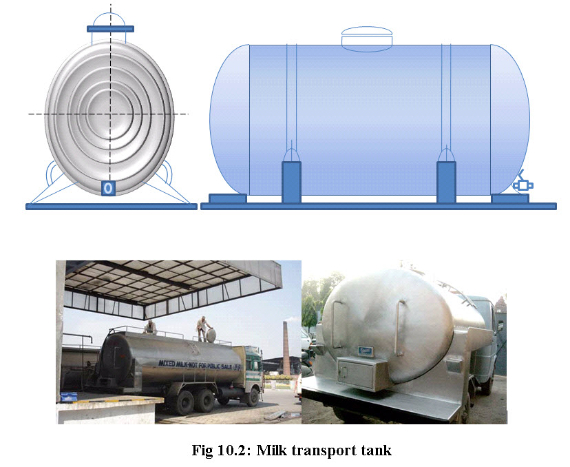
Handling the milk in cans is slow and laborious when the larger quantities are to be handled. Road truck/ trailers or rail tankers are convenient options in such cases.
- Capacity: 500 to 12000 ltr.
- The size and the type depend upon.
-
Amount of milk to be transported
-
Road condition
-
Comparative cost
-
10.1.1.1 Difference between Truck and Trailer
|
Truck |
Trailer |
|
Easy to travel in tighter places |
Suitable for long distances and wide roads. |
|
Carry less |
Pull more. |
10.1.1.2 Construction of Milk Transport Tank
The milk transport tanks are generally having the similar type of construction, with some modifications based upon requirements and convenience.
- Material of construction:
Inner shell- Stainless Steel (18% chromium, 8% Nickel)
Smooth welding
Polished surface
Rounded corners & edges
Insulation- cork, plastic, foam, mineral wool.
Outer jacket—ordinary carbon steel, Aluminum, S.S,
|
Ordinary carbon steel |
Stainless Steel |
|
Low cost |
High cost |
|
High maintenance |
High demand
|
Different milks can be transported at once
Low agitation
Distribute load over Axle.
- Accessories or mountings:
Manhole, air vent and cover assembly required for inspection
Sanitary cover is having sanitary rubber gasket and locking device.
Air vent → to “breath” → prevent pressure and vacuum during loading or unloading.
Outlet valve with covered cabinet which can be sealed properly.
Ladder- to climb on tank for cleaning or inspection
Hoses - Rubber or translucent Plastic, Puncture & collapse resistant, sanitary cap/Plug at dead end.
10.1.2 Milk Storage Tanks
Storage tanks are used on dairy plants for the storage of raw, pasteurized or processed products, often in very large volumes. Milk is stored up to 72 hrs. between reception and processing in this most important part of any dairy plant, during this period the milk is also held below the temperature 7 oC or below.
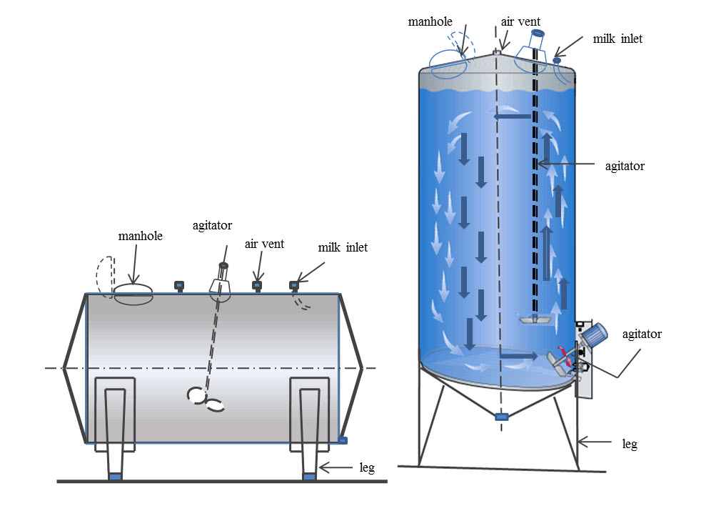
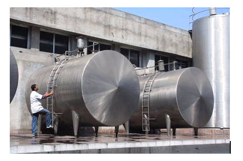
Fig 10.3: Cylindrical milk storage tanks in a horizontal and vertical design
The design and construction of the tanks should be such that it provides ease of CIP as well as sanitizing. The major constructional and design features are as follows:
-
Smooth surface inside made up of 18:8 type Stainless Steel (18% chromium, 8% nickel)
-
May be horizontal, vertical, Oval or cylindrical
|
Horizontal |
Vertical |
|
Less head required |
High Head required |
|
More floor space required |
Less floor space required |
-
Capacity- up to 2,00,000 ℓ
-
Fitted on Adjustable legs (Ball feet)
-
Construction :-
- Inner S.S shell (18:8 type s.s.)
- Outer jacket (mild steel or s.s)
- Insulation (5-7.5 cm thick)
- Minimum contact of metals between inner & outer shell inorder to reduce heat transfer/ heat loss
- Accessories or mountings:
- Man hole - with diameter 450mm.
-Inside outside Swing type door where weight of products aids in the sealing.
Foam free inlet but better to fill from below to achieve better CIP and less foaming.
Head Space: 15 cm for viewing ports and lights and also for CIP systems.
Air vent: At the top of the tank which prevent vacuum or pressure during loading or unloading respectively. It should have screen to prevent entry of dust and design should be such that no water shall penetrate.
Sampling valve is kept on man hole door.
Thermometer probe is inserted in to s.s. well which is welded inside.
Plug type valve for sanitary design and full opening area.
Agitator is provided to mix product for standardization, cooling etc.
- Horizontal agitator requires: - oil free bearings
- Rotary seals
- Vertical agitator requires step bearings at bottom due to length
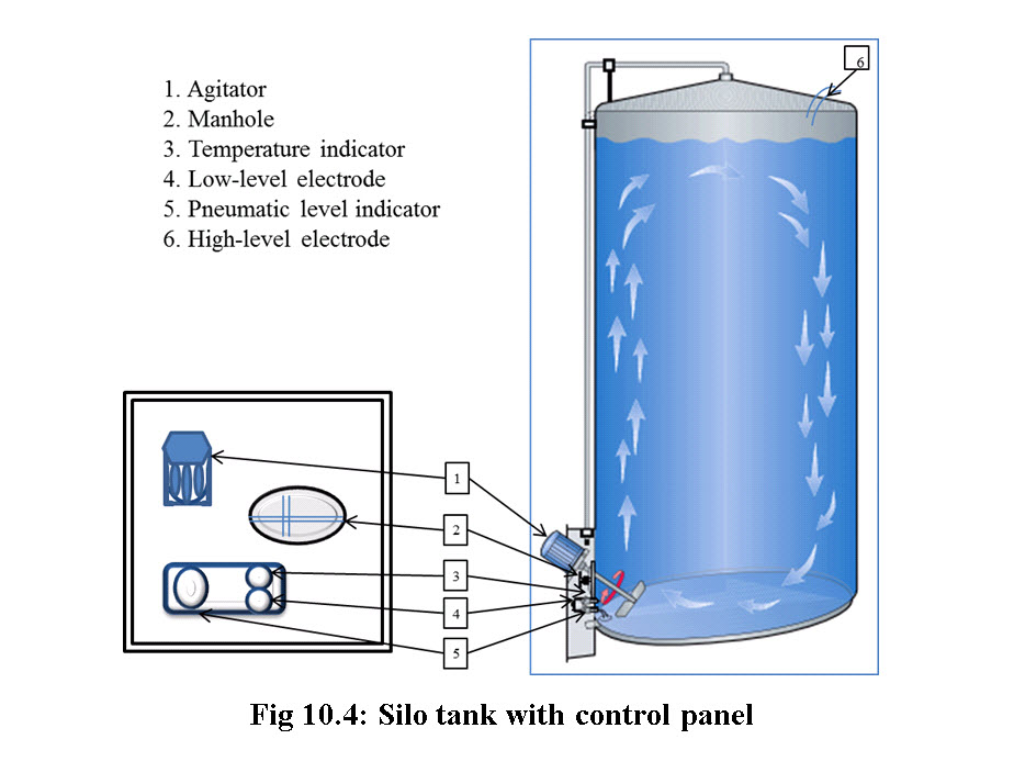
10.1.3 Silo Tank:-
Silo tanks are used to handle larger quantities of product in a limited ground area. Normally its capacity ranges from 50,000 to 1,00,000 ltrs.
- Tanks can be kept outside to reduce the building cost.
- Silo walls have double wall construction with a minimum 70 mm thick insulation of mineral wool.
- Outer shell can be made up of stainless steel but to reduce the cost mild steel with anti-corrosion paint can be used.
- In order to make complete drainage easy, the bottom of tank slop is downwards with an inclination of about 6o towards outlets.
- Agitator:-Electrodes to stop-start agitators as per level, as well as to control overflow are provided
-
Are provided to avoid cream separation at the top during storage
-
One or two agigators can be installed based upon the size of silo.
-
Agitator must not be started before level of milk is above it to avoid splashing and whipping.
-
- Temperature and level indicators are provided on control panel.
 10.2 Homogenization
Milk is an oil-in-water emulsion with the fat globules dispersed in a continuous serum phase. If raw milk is allowed to stand, the fat would rise and form a cream layer. Homogenization is a mechanical treatment of the fat globules achieved by passing milk under high pressure through a thin slit, which results in stability of milk due to a decrease in the average diameter and an increase in number and surface area, of the fat globules. Three factors contribute to this enhanced stability of homogenized milk: a decrease in the mean diameter of the fat globules (a factor in Stokes Law), a decrease in the size distribution of the fat globules (causing the speed of rise to be similar for the majority of globules such that they don't tend to cluster during creaming) and an increase in density of the globules (bringing them closer to the continuous phase) owing to the adsorption of a protein membrane.
10.2.1 Homogenization Mechanism
Auguste Gaulin's patent in 1899 consisted of a 3 piston pump in which product was forced through one or more hair like tubes under pressure. It was discovered that the size of fat globules produced were 500 to 600 times smaller than tubes. There have been over 100 patents since, all designed to produce smaller average particle size with expenditure of as little energy as possible. The homogenizer consists of a 3 cylinder positive piston pump and homogenizing valve. The pump is turned by electric motor through connecting rods and crankshaft. To understand the mechanism, consider a conventional homogenizing valve processing an emulsion such as milk at a flow rate of 20,000 ℓ/hr. at 14 MPa (2100 psig). As it first enters the valve, liquid velocity is about 4 to 6 m/s. It then moves into the gap between the valve and the valve seat and its velocity is increased to 120 m/s in about 0.2 ms. The liquid then moves across the face of the valve seat (the land) and exits in about 50 µs. The homogenization phenomena is completed before the fluid leaves the area between the valve and the seat, and therefore emulsification is initiated and completed in less than 50 µs. The whole process occurs between 2 pieces of steel in a steel valve assembly. The product may then pass through a second stage valve similar to the first stage. While most of the fat globule reduction takes place in the first stage, there is a tendency for clumping or clustering of the reduced fat globules. The second stage valve permits the separation of those clusters into individual fat globules.
It is most likely that a combination of two theories, turbulence and cavitation, explains the reduction in size of the fat globules during the homogenization process.
10.2.1.1 Turbulence
Energy, dissipating in the liquid going through the homogenizer valve, generates intense turbulent eddies of the same size as the average globule diameter. Globules are thus torn apart by these eddie currents reducing their average size.
10.2.1.2 Cavitation
Considerable pressure drop with charge of velocity of fluid. Increased pressure increases velocity. Liquid cavitates because its vapour pressure is attained. Cavitation generates further eddies that would produce disruption of the fat globules. The high velocity gives liquid a high kinetic energy which is disrupted in a very short period of time.. Dissipation of this energy leads to a high energy density (energy per volume and time). Resulting diameter is a function of energy density. In summary, the homogenization variables are:
type of valve
pressure
single or two-stage
fat content
surfactant type and content
viscosity
temperature
Also to be considered are the droplet diameter (the smaller, the more difficult to disrupt), and the log diameter which decreases linearly with log P and levels off at high pressures.
10.2.2 The homogeniser
High-pressure homogenisers are generally needed when high-efficiency homogenisation is required.
The product enters the pump block and is pressurised by the piston pump. The pressure that is achieved is determined by the back-pressure given by the distance between the forcer and seat in the homogenisation device.
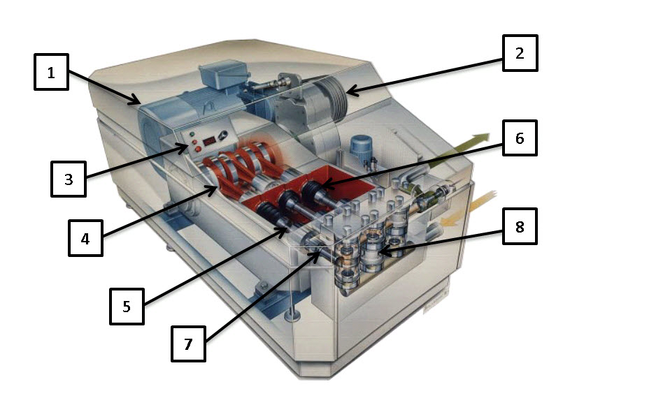
Fig 10.5: The homogeniser is a large high-pressure pump with a homogenising device.
1 Main drive motor
2 V-belt transmission
3 Pressure indication
4 Crankcase
5 Piston
6 Piston seal cartridge
7 Solid stainless steel pump block
8 Homogenising valve assembly
10.2.2.1 The high-pressure pump
The piston pump is driven by a powerful electric motor [1] in figure 10.5, through a crankshaft and connecting-rod transmission which converts the rotary motion of the motor to the reciprocating motion of the pump pistons. The pistons [5], run in cylinders in a high-pressure block. They are made of highly resistant materials. The machine is fitted with double piston seals. Water is supplied to the space between the seals to cool the pistons.
10.2.2.2 The homogenisation device
Figures 10.6 shows the homogenisation and hydraulic system. The piston pump boosts the pressure of the milk from about 300 kPa (3 bar) at the inlet to a homogenisation pressure of 10 – 25 MPa (100 – 250 bar) depending on the product. The inlet pressure to the first stage before the device (the homogenisation pressure) is automatically kept constant. The oil pressure on the hydraulic piston and the homogenisation pressure on the forcer balance each other. The homogeniser is equipped with one common oil tank, whether it has one or two stages. However, in two-stage homogenisation there are two oil systems, each with its own pump. A new homogenisation pressure is set by changing the oil pressure. The pressure can be read on the high-pressure gauge.
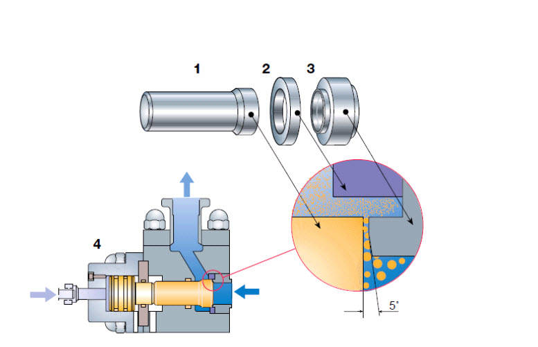
Fig 10.6: The components of a single stage homogenisation device.
1 Forcer
2 Impact ring
3 Seat
4 Hydraulic actuator
Homogenisation always takes place in the first stage. The second stage basically serves two purposes:
• Supplying a constant and controlled back-pressure to the first stage, giving best possible conditions for homogenisation;
• Breaking up clusters formed directly after homogenisation.
The parts in the homogenisation device are precision ground. The impact ring is attached to the seat in such a way that the inner surface is perpendicular to the outlet of the gap. The seat has a 5° angle to make the product accelerate in a controlled way, thereby reducing the rapid wear and tear that would otherwise occur.
Milk is supplied at high pressure to the space between the seat and forcer. The width of the gap is approximately 0.1 mm or 100 times the size of the fat globules in homogenised milk. The velocity of the liquid is normally 100 – 400 m/s in the narrow annular gap, and homogenisation takes place in 10 – 15 µs. During this time all the pressure energy delivered by the piston pump is converted to kinetic energy. Part of this energy is converted back to pressure again after the device. The other part is released as heat; every 40 bar in pressure drop over the device gives a temperature rise of 1°C. Less than 1% of the energy is utilised for homogenisation, but nevertheless high pressure homogenisation is the most efficient method available.
10.2.3 Effects of Homogenization:
10.2.3.1 Fat globule
The table shows the major changes occurs in the fat globules during the homogenization process.
|
|
No Homogenization |
15 MPa (2500 psi) |
|
Av. diam. (μ m) |
3.3 |
0.4 |
|
Max. diam. (μ m) |
10 |
2 |
|
Surf. area (m2/ml of milk) |
0.08 |
0.75 |
|
Number of globules (per μm-3) |
0.02 |
12 |
10.2.3.2 Surface layer
The milk fat globule has a native membrane, picked up at the time of secretion, made of amphiphilic molecules with both hydrophilic and hydrophobic nature. This membrane lowers the interfacial tension resulting in a more stable emulsion. During homogenization, there is a tremendous increase in surface area and the native milk fat globule membrane (MFGM) is lost. However, there are many amphiphilic molecules present from the milk plasma that readily adsorb: casein micelles (partly spread) and whey proteins. The interfacial tension of raw milk is 1-2 mN/m, immediately after homogenization it is unstable at 15 mN/m, and shortly becomes stable (3-4 mN/m) as a result of the adsorption of protein. The transport of proteins is not by diffusion but mainly by convection. Rapid coverage is achieved in less than 10 s but is subject to some rearrangement.
10.2.3.3 Advantages of Homogenization:
Smaller fat globules leading to no cream-line formation,
Whiter and more appetizing colour,
Reduced sensitivity to fat oxidation,
More full-bodied flavour, better mouthfeel,
Better stability of cultured milk products.
10.2.3.4 Disadvantages of Homogenization:
Homogenised milk cannot be efficiently separated.
Somewhat increased sensitivity to light – sunlight and fluorescent tubes – can result in “Sunlight flavour” (see also chapter 8, Pasteurised milk products).
Reduced heat stability, especially in case of single-stage homogenisation, high fat content and other factors contributing to fat clumping.
The milk will not be suitable for production of semi-hard or hard cheeses because the coagulum will be too soft and difficult to dewater.
Last modified: Thursday, 22 August 2013, 5:56 AM