Site pages
Current course
Participants
General
Module 1_Fundamentals of GW
Module 2_Well Hydraulics
Module 3_Design, Installation and Maintenance of W...
Module 4_Groundwater Assessment and Management
Module 5_Principle, Design and Operation of Pumps
Module 6_Performance Characteristics, Selection an...
Keywords
Lesson 23 Introduction to Pumping System
23.1 Basic Mechanisms of Water Lifting
When the source of water is at a lower than the area to be irrigated and when free gravity flow is not available to drain surface or subsurface water, the water lifting devices are used. Water may be moved by the application of any one (or any combination) of the six following mechanical principles, which are mostly independent (FAO, 1986):
-
Direct lift: This involves physically lifting water in a container.
-
Displacement: This involves utilizing the fact that water is effectively incompressible and hence it can be ‘pushed’ or displaced.
-
Velocity head creation: When water is propelled to a high speed, the momentum can be used either to create a flow or to create a pressure.
-
Buoyancy of a gas: Air or other gases bubbled through water will cause movement of columns of water due to difference in specific gravity.
-
Impulse: Water hammer phenomenon creates impulse due to which a small portion of the water supply is lifted to a considerably high level.
-
Gravity: Water flows downward under the influence of gravity.
23.2 Types of Water Lifting Devices
Several types of indigenous water lifts are in use in small-scale irrigation. These families of lifting or propelling devices and pumps may be classified according to which of the above principles they depend on. Table 23.1 is an attempt to classify pumps under the categories given above. It is apparent from this table that most categories sub-divide into further classifications viz., ‘reciprocating’ or ‘cyclic’ and ‘rotary’. The first category of these classifications relates to the devices that are cycled through a water-lifting operation (e.g., a bucket on a rope is lowered into the water, dipped to make it fill, lifted, emptied and then the cycle is repeated); in such cases the water output is usually intermittent, or at the best pulsating rather than continuous. Rotary devices were generally developed to allow a greater throughput of water, and they also are easier to couple to engines or other types of mechanical drive. Therefore, by definition, a rotary pump will generally operate without any reversal or cessation of flow, though its output may appear in spurts or pulsations in some cases (FAO, 1986).
Table 23.1. Taxonomy of water lifting devices (Source: FAO, 1986)
|
Category and Name |
Type of Constr -uction |
Head Range (m) |
Power Range (W) |
Output |
Efficiency |
Cost |
Suction Lift? |
Status for Irrigation |
|
1. DIRECT LIFT DEVICES |
||||||||
|
1. Reciprocating/Cyclic: - Watering can - Scoops and bailers - Swing basket - Pivoting gutters and “dhones” - Counterpoise lift or “shadoof” - Rope & bucket and windlass - Self-emptying bucket or “mohte” - Reciprocating bucket hoist |
1 1 1 2 2 1 2 3 |
>3 >1 >1 1-1.5 1-4 5-50 3-8 100-500
|
* * * * * * ** **** |
* ** ** ** ** * *** **** |
* * * ** ** * * *** |
* * * ** ** * ** ***** |
x x x x x x x x
|
√ √ √ √ √ √ √ x |
|
2. Rotary/Continuous - Continuous bucket pump - Persian wheel or “tablia” - Improved Persian wheel “zawaffa” - Scoop wheels or “sakia” - Waterwheels or “noria” |
2 2 2
2 2
|
5-50 3-10 3-15
>2 >5 |
** ** ***
** * |
** *** ****
**** ** |
*** *** ****
**** ** |
** ** ***
**** ** |
x x x
x x |
√ √ √
√ √ |
|
II. DISPLACEMENT PUMP |
||||||||
|
1. Reciprocating/Cyclic - Piston/bucket pumps - Plunger pumps - Diaphragm pumps - “Petropump” - Semi-rotary pumps - Gas or vapor displacement |
2&3 3 3 3 3 3 |
2-200 100-500 5-10 10-100 5-10 5-50 |
*** *** ** ** * **** |
*** ** *** ** ** **** |
***** **** **** ***** ** *** |
**** ***** *** **** ** *** |
√ √ √ √ √ √ or x |
√ ? √ ? x ? |
|
2. Rotary/Continuous - Gear and lobe pumps - Flexible vane pumps - Progressive cavity (Mono) - Archimedean screw - Open screw pumps - Coil and spiral pumps - Flash-wheels & treadmills - Water-ladders “dragon spines” - Chain (or rope) and washer - Peristaltic pump - Porous rope |
3 3 3 3 3 2 2 & 3 2 2 & 3 3 3
|
10-20 10-20 10-100 >2 >6 >6 >2 >2 3-20 >3 3-10 |
* ** *** ** **** ** ** ** *** * **
|
* *** *** **** ***** ** **** *** *** * **
|
** *** **** *** **** *** ** *** **** *** ? |
*** **** **** *** ***** *** ** *** **** *** ? |
√ √ x x x x x x x √ X |
x x ? √ √ √ √ √ √ x ?
|
|
III. VELOCITY PUMPS |
||||||||
|
1. Reciprocating/Cyclic - Inertia and “joggle” pumps - Flap valve pump - Resonating joggle pump - Rebound inertia |
2 & 3 1 & 2 2 3 |
2-4 2-4 2-10 2-60 |
* * ** ** |
** * **** * |
**** ** **** **** |
** * *** *** |
x x x √ |
√ √ ? x
|
|
2. Rotary/Continuous - Propeller (axial flow) pumps - Mixed flow pumps - Centrifugal (volute) pumps - Centrifugal (turbine) pumps - Centrifugal (regenerative) pumps - Jet pumps (water, air or stream) |
3 3 3 3 3 3 |
5-3 2-10 3-20+ 3-20+ 10-30 2-20
|
**** **** ***** ***** *** *** |
***** ***** ***** ***** *** *** |
**** **** **** **** *** ** |
**** **** *** **** **** *** |
x x √ √ √ x
|
√ √ √ √ x x |
|
IV. BUOYANCY PUMPS |
||||||||
|
Air Lift |
3 |
5-50 |
** |
*** |
** |
**** |
X |
x |
|
V. IMPULSE PUMPS |
||||||||
|
Hydraulic Ram (Hydram) |
3 |
10-100 |
** |
** |
*** |
*** |
X |
√ |
|
VI. GRAVITY DEVICES |
||||||||
|
Syphon |
1, 2 & 3 |
1-(-10) |
- |
***** |
- |
** |
- |
√ |
|
Qantas or Foggara |
2 |
- |
- |
** |
***** |
- |
- |
√ |
Note: Construction Type: 1: Basic; 2: Traditional; 3: Industrial.
*: Very Low; **: Low Medium; ***: Medium, ****: Medium-high; *****: High.
√: Yes; x: No; ?: Possible; X: Unlikely.
23.3 Hydraulic Ram
23.3.1 Introduction
Hydraulic ram (or hydram) is a special type of pump, which utilizes the energy of a large quantity of water falling through a small height to lift a small quantity of this water to a much greater height. Therefore, no external power is required to operate this pump. The first hydram was invented in 1775 by John Whitehurst of Derby, England (Lal, 1969). Thus, hydram can be employed when some natural source of water like a spring or a stream is available at some altitude (e.g., in hilly regions). It can be used wherever a stream of water flows with a minimum of about 1 m fall in altitude (Michael and Khepar, 1999). It can also be used for water supply to countryside and remote areas where a water source having a large quantity of water at some height is available, but the power is scarce or not available so that other types of pumps cannot be used. The simplicity of construction and the automatic operation of the hydram make it particularly suitable for remote rural areas in a hilly region which often suffer from non-availability of commercial power sources (e.g., electricity or diesel) and lack of skilled technicians for the repair and maintenance of pumps and prime movers.
The hydram can be used for various purposes such as irrigation in sloping lands, domestic water supply in villages, water supply to small industries and fish ponds in hilly areas, supplying water to a high-level field channel in undulating hills, and boosting the discharge of lift irrigation schemes in hilly areas by taking part of the pump discharge to higher elevations for irrigation.
23.3.2 Main Components of Hydram
A hydraulic ram consists of a valve chamber (also called ‘hydram chamber’ or ‘hydram body’) having a waste valve and a delivery valve (Fig. 23.1). The waste valve opens into a waste water channel and the delivery valve opens into an air vessel to which a delivery pipe is connected which carries water to a water storage tank located at a higher elevation. The valve chamber is connected to a water supply tank through a supply pipe. The supply pipe is fitted with a gate valve to operate the hydraulic ram. Figures 23.2(a, b) illustrate two typical designs of a hydraulic ram.
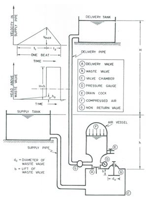
Fig. 23.1. Components and operating principle of a hydraulic ram.
(Source: Modi and Seth, 1998)
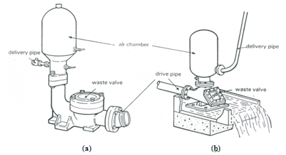
Fig. 23.2 (a,b). Typical designs of hydraulic rams: (a) Traditional European hydram design; (b) South-East Asia type of hydram. (Source: FAO, 1986)
23.3.3 Working Principle of Hydram
The hydram works on the principle of water hammer or inertia pressure developed in the supply pipe. Thus, in principle, it is an impulse pump. The momentum of a long column of water flowing through the supply pipe is made to force a part of the water to a height greater than that of the supply source itself. In order to develop maximum impulse, the supply pipe should be as long as possible. Installation of a hydram too close to the source of supply will reduce the impulse, and hence the delivery head.
23.3.4 Operation of Hydram
Initially, the water is at rest and the delivery valve and waste valve are closed (Fig. 23.1). The hydram is started by opening the gate valve of the supply pipe, thereby setting the water in motion. The column of water in the supply pipe rebounds a short distance creating partial vacuum in the valve chamber (hydram chamber). It causes the waste valve to open due to its own weight. Thus, water begins to escape through the waste valve into a waste water channel. As discharge through the waste valve increases, the flow of water in the supply pipe accelerates (i.e., velocity of flow increases). The acceleration of the water column in the supply pipe causes inertial pressure due to which pressure in the valve chamber increases. The pressure in the valve chamber rapidly increases to such an extent at which the dynamic thrust (due to the accelerating flow) acting on the lower face of the waste valve is greater than the weight of the waste valve. Consequently, the waste valve closes rapidly (i.e., instantaneously), which produces water hammer in the supply pipe. A very high pressure is momentarily produced in the valve chamber, by which the delivery valve is forced to open. The water then flows from the supply tank through the delivery valve into the air vessel and the delivery pipe (Fig. 23.1). Thus, some of the water flowing through the delivery valve is directly supplied to the water storage tank and some of it is stored in the air vessel. The water flowing into the air vessel compresses the air inside it, which pushes a part of the water in the delivery pipe even when the delivery valve is closed. Thus, an air vessel of a hydram helps provide a continuous delivery of water at a more or less uniform rate.
As the pressure gradually rises in the air chamber, inflowing water is brought to rest and the delivery valve then closes and the waste valve opens (due to the reduced pressure in the valve chamber), which again causes the water to flow from the supply tank to the waste water channel. This constitutes one cycle of operation or one beat of the hydram (Fig. 23.1). The same cycle is then repeated until the water supply is stopped. The operation of the hydraulic ram can be stopped by closing the gate valve fitted to the supply pipe.
It should be noted that the operation of a hydram depends on the successful creation and destruction of velocity of flow in the supply pipe. The waste valve must close suddenly to enable kinetic energy to be utilized to a maximum extent. Theoretically, the pumping head remains constant during the operation.
23.3.5 Analysis of Hydram Operation
With reference to Fig. 23.1, let:
d = diameter of the supply pipe,
do = diameter of the waste valve,
b = lift of the waste valve,
W = weight of the waste valve, and
Vo = velocity of flow of water through the waste valve just before its closure.
The dynamic pressure head acting on the waste valve is given as:
![]() (23.1)
(23.1)
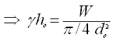
Also, just before the closure of the waste valve, the force acting vertically upwards on the waste valve is equal to the weight of the waste valve. That is,
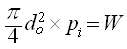 (23.2)
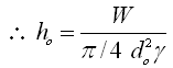
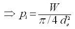 (23.3)
 (23.4)
 (23.5)
If Vmax = maximum velocity of flow of water in the supply pipe just before the closure of the waste valve, then by the continuity equation we have:
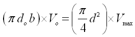 (23.6)
Also, if t1 = time required to build up the velocity of water flow in the supply pipe from 0 (zero) to the maximum velocity (Vmax) or, it is the time for which the waste valve remains open during each beat, then from the principle of water hammer we have:
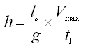 (23.7)
Where, h = water-level in the supply tank above the waste valve and ls = length of the supply pipe.
Similarly, if t2 = time during each beat for which the waste valve remains closed, or the delivery valve remains open and H = water-level in the delivery tank above the water-level in the supply tank, then
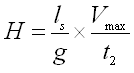 (23.8)
Thus, the time taken to complete one cycle (or one beat) is t, i.e., t = t1 + t2 (Fig. 23.1) which can be calculated as:
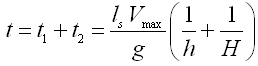 (23.9)
Furthermore, if q = discharge of water lifted by the hydram, Q = discharge of water flowing through the waste valve and the mean velocity of flow in the supply pipe is Vmax/2, then q and Q can be computed as follows:
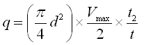 (23.10)
and
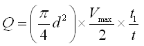 (23.11)
It should be noted that the loss of head due to friction in the supply and delivery pipes has been neglected in Eqns. (23.7) and (23.8). However, considering this head loss, Eqns. (23.7) and (23.8) can be modified as follows:
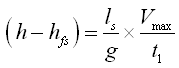 (23.12)
and
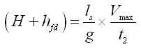 (23.13)
Where, hfs and hfd are head losses due to friction in supply and delivery pipes, respectively.
23.3.6 Efficiency of a Hydram
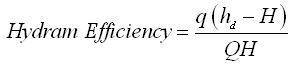
The overall efficiency of a hydram is generally calculated in two ways: Rankine’s approach and D’Aubuisson’s approach. In the Rankine’s approach, the water surface in the supply reservoir is considered as a datum for calculating delivery head and the base of the waste valve (i.e., top of the hydram chamber) is considered as a datum for calculating supply head. Hence, the input energy during one cycle is gQh, and the useful output energy during the same cycle is gqH, where g = unit weight of water. Thus, the Rankine’s Efficiency is given as:
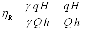 (23.14)
On the other hand, in the D’Aubuisson’s approach, the datum is taken as the base of the waste valve (i.e., top of the hydram chamber) and hence, the energy input during one cycle is g (Q+q) h and the useful output during the same cycle is gq (H+h). Thus, the D’Aubuisson’s efficiency is given as:
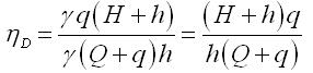 (23.15)
Note that the value of the D’Aubuisson’s efficiency is always greater than the Rankine’s efficiency. Because of significant energy losses in a hydram, its maximum efficiency is generally limited to about 70-75% (Lal, 1969). The main causes of energy losses are major and minor friction head losses in the supply and delivery pipes as well as minor friction head losses in the valves, and the kinetic energy wasted due to large flow through the waste valve.
It is worth mentioning that in Eqns. (23.14) and (23.15), friction head losses have been neglected. If these losses are taken into account, then the variables h and H appearing in the above equations should be replaced with (h - hfs) and (H + hfd), respectively.
23.3.7 Advantages of Hydraulic Ram
(i) No power source is needed to operate a hydram.
(ii) It requires no lubrication and no packing as there are no moving elements.
(iii) Maintenance cost is very low and almost no labor is required for supervision.
(iv) Hydrams can work continuously for 24 hours, and thus can provide a regular water supply.
(v) Hydrams can be adjusted to work with any quantity from their maximum capacity to less than one-half, and automatic adjustment is possible.
(vi) It has relatively high efficiency and reliability.
(vii) It has a long service life.
23.3.8 Criteria for Site Selection for Hydraulic Ram Installation
The selection of a suitable site, careful planning of various components of the system, and adherence to correct procedures in installation and maintenance contribute substantially to the economics and efficiency of a hydraulic ram. The following points should be taken into account while selecting a site for installing a hydraulic ram for irrigation or water supply (Michael and Khepar, 1999):
-
Quantity of water available in the stream during the cropping seasons and lean periods of flow.
-
Available fall in the stream (i.e., supply head).
-
Elevations of the water-supply points in the area proposed to be brought under irrigation and/or the elevation of the water storage tank.
-
Distance of the ultimate delivery point of water from the proposed site of the hydraulic ram.
-
Safe distance from the path of possible landslides and avalanches in hilly areas.
-
Possibility of stable foundation for the hydram, intake tank and a stable bed for the drive pipe.
-
Total area proposed to be brought under irrigation or proposed population to be served and the ancillary requirement of the community.
-
Existing and proposed cropping patterns of the area to be irrigated.
-
Estimated requirement of irrigation water.
-
Expected rainfall in terms of amount and periods of occurrence to estimate shut-off periods if the hydram is used exclusively for irrigation.
23.3.9 Example Problem on Hydram
Problem (Michael and Khepar, 1999): Assuming the following conditions, estimate the minimum expected flow rate of the source of water for installing a hydraulic ram in a rural water supply scheme:
Vertical fall = 9 m; Vertical lift = 60 m;
Population of village = 200; Growth rate = 25% in 15 years;
Water requirement = 45 L/day/person; and Efficiency of hydram = 60%.
Solution: Estimated population of the village after 15 years at the growth rate of 25% =, and Water demand = 250 × 45 = 11250 L/day.
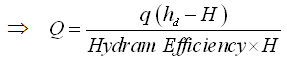
Now, the minimum expected flow rate of the water source for a hydram can be calculated using the Rankine’s formula [Eqn. (23.14)], which is given as:
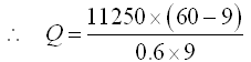 = 106250 L/day = 1.23L/s, Ans.
Note that in case the minimum rate of flow of the source of supply is lower than the computed value, it is still possible to get the desired output of water at the delivery. It can be possible by increasing the vertical fall or reducing the vertical lift, or by resorting to alternate locations and alignment.
23.4 Defining Pump
Pump can be broadly defined as ‘a mechanical device to increase the pressure energy of a fluid’. Pumps are mostly used for lifting fluids (liquids or gases) from a lower level to a higher level. This is achieved by creating a low pressure at the inlet or suction end and a high pressure at the outlet or delivery end of the pump. Because of the low inlet pressure, the fluid rises from a depth where it is available and the high outlet pressure forces the fluid to a desired height. Here, work is done by a prime mover on the pump to enable it to impart energy to the fluid.
23.5 Classification of Pumps
Pumps are classified into two basic groups based on the method by which energy is imparted to the fluid. They are: positive displacement pumps and rotodynamic pumps. The positive displacement pumps are classified into two major groups: reciprocating pumps and rotary pumps, which are further classified into different groups as shown in Fig. 23.3. On the other hand, rotodynamic pumps are broadly classified into radial flow pumps, axial-flow pumps and mixed-flow pumps according to the direction of fluid flow inside the pump (Fig. 23.3). Radial flow pumps are further classified as volute pumps and diffusion (turbine) pumps based on the design of pump casing, both of which can be either of single stage (having one impeller) or multi stages (having more than one impellers), though most multi-stage pumps consist of diffusion casing.
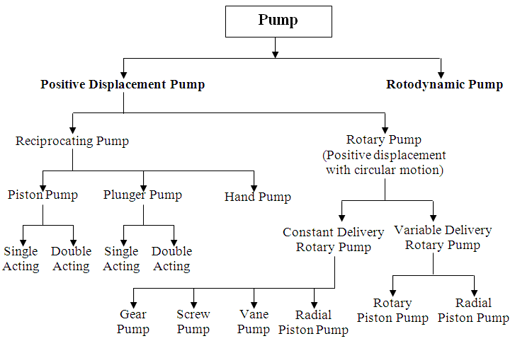
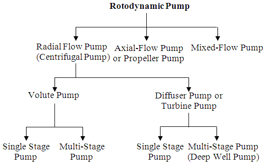
Fig. 23.3. Classification of different types of pumps.
23.5.1 Positive Displacement Pumps
These are the pumps in which the liquid is sucked and then it is actually pushed due to the thrust exerted on it by a moving element which results in lifting the liquid to a desired height. As such the discharge of liquid pumped by these pumps almost fully depends on the speed of the pump. The most common example of the positive displacement pump is reciprocating pumps. For the details of positive displacement pumps, the readers are referred to Michael and Khepar (1999) and Modi and Seth (1998).
23.5.2 Rotodynamic Pumps
They have a rotating element (called ‘impeller’) through which when the liquid passes, its angular momentum changes which results in an increase of the pressure energy of the liquid. Thus, a rotodynamic pump does not push the liquid as in the case of a positive displacement pump. The most common example of a rotodynamic pump is centrifugal pumps. The details about centrifugal pumps are given in Lessons 24 to 32, together with important references for further reading.
Note that the use of reciprocating pumps has become out of date for the water supply purpose, except for some popular indigenous water lifting devices used in rural areas. Rotodynamic pumps, especially of centrifugal type, have almost totally replaced the reciprocating pumps for lifting water.
References
-
FAO (1986). Water Lifting Devices. FAO Irrigation and Drainage Paper 43, Food and Agriculture Organization of the United Nations, Rome, Italy.
-
Lal, J. (1969). Hydraulic Machines. Metropolitan Book Co. (Pvt.) Ltd., Delhi.
-
Michael, A.M. and Khepar, S.D. (1999). Water Well and Pump Engineering. Tata McGraw-Hill Publishing Co. Ltd., New Delhi.
-
Modi, P.N. and Seth S.M. (1998). Hydraulics and Fluid Mechanics. Twelfth Edition, Standard Book House, New Delhi.
Suggested Readings
-
Michael, A.M. and Khepar, S.D. (1999). Water Well and Pump Engineering. Tata McGraw-Hill Publishing Co. Ltd., New Delhi.
-
Murty, V.V.N. and Jha, M.K. (2011). Land and Water Management Engineering. Sixth Edition, Kalyani Publishers, Ludhiana.
-
Lal, J. (1969). Hydraulic Machines. Metropolitan Book Co. (Pvt.) Ltd., Delhi.
-
Modi, P.N. and Seth S.M. (1998). Hydraulics and Fluid Mechanics. Twelfth Edition, Standard Book House, New Delhi.
Last modified: Friday, 14 March 2014, 11:42 AM