Site pages
Current course
Participants
General
Module 1:Water Resources Utilization& Irrigati...
Module 2:Measurement of Irrigation Water
Module 3: Irrigation Water Conveyance Systems
Module 4: Land Grading Survey and Design
Module 5: Soil –Water – Atmosphere Plants Intera...
Module 6: Surface Irrigation Methods
Module 7: Pressurized Irrigation
Module 8: Economic Evaluation of Irrigation Projec...
Topic 9
LESSON 11 Open Channel Flow
There are two kinds of flow: Open channel and pipe. These flows differ in many ways. The important difference is that open channel flow has free water surface whereas pipe flow does not have free water surface.
11.1 Open Channels
Irrigation water is conveyed in either open channel or closed conduits. Open channels receive water from natural streams or underground water and convey water to the farm for irrigation. Open channels have free surface. The free surface is subjected to atmospheric pressure. The basic equations used for water flow in open channels are continuity equation, Bernoulli equation and Darcy Weisbach equation.
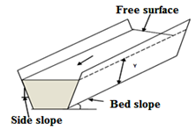
Fig. 11.1. A trapezoidal shaped open channel.
(Source: www.nptel.iitm.ac.in/courses/105107059/module1/.../lecture1.pdf)
11.2 Types of Open Channels
(a) Prismatic and Non-Prismatic Channels
A channel in which the cross sectional shape, size and the bottom slope are constant over long stretches is termed as prismatic channel. Most of the man-made or artificial channels are prismatic channels. The rectangular, trapezoidal (Fig. 11.2), triangular and half-circular are commonly used shapes in manmade channels. All natural channels generally have varying cross section and consequently are nonprismatic.
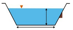
Fig. 11.2. Sketch of a prismatic channel.
(Source: www.nptel.iitm.ac.in/courses/105107059/module1/.../lecture1.pdf)
(b) Rigid and Mobile Boundary Channels
Rigid channels are those in which the boundary or cross section is not deformable. The shape and roughness magnitudes are not functions of flow parameters. The lined channels and non erodible unlined channels are rigid channels. In rigid channels the flow velocity and shear stress distribution are such that no major scouring, erosion or deposition takes place in the channel and the channel geometry and roughness are essentially constant with respect to time. Channels are classified as mobile channels when the boundary of the channel is mobile and flow carries considerable amounts of sediment through suspension and is in contact with the bed. In the mobile channel, depth of flow bed width, longitudinal slope of channel may undergo changes with space and time depending on type of flow.The resistance to flow, quantity of sediment transported and channel geometry all depend on interaction of flow with channel boundaries.
11.3 Types of Open Channel Flow
Open channel flow can be classified into many types and described in various ways. The following section describes classification based on variation of flow properties such as depth of flow, velocity etc. with respect to time and space.
a) Steady and Unsteady Flows
Flow is steady if the velocity and depth are constant with respect to time. If the depth velocity or discharge changes with time, the flow is termed as unsteady.
Flood flows in rivers and rapidly varying surges in canals are examples of unsteady flow.
b) Uniform and Non-Uniform Flows
If the flow properties, say the depth of flow and discharge in an open channel remain constant along the length of the channel, the flow is said to be uniform. A prismatic channel carrying a certain discharge with a constant velocity is an example of uniform flow.
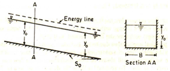
Fig. 11.3. Uniform flow in a prismatic channel.
(Source: Subramanya, 2000)
If the flow properties such as depth and discharge vary with distance along the channel is termed as non-uniform flow
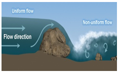
Fig. 11.4. Uniform and non-uniform flows.
(Source: www.wegc203116.unigraz.at/meted/hydro/basic/ Routing/print Version/03-streamflow_characteristics.htm)
Fig. 11.4 shows a view of uniform and non uniform flow. In uniform flow, the gravity force on the flowing water balances the frictional force between the flowing water and inside surface of the channel, which is in contact with the water. In case of non-uniform flow, the friction and gravity forces are not in balance.
The flow in open channel can be steady or unsteady. It can be uniform or non -uniform. A non-uniform flow is also termed as varied flow. Steady and unsteady flows can be uniform or varied.
c) Gradually Varied and Rapidly Varied Flow
The non-uniform flow can be classified as gradually varied flow (GVF) and rapidly varied flow (RVF). Varied flow assumes that no flow is externally added to or taken out of channel system and hence the volume of water in a known time interval is conserved in the channel system and hence the volume of water in a known time interval is conserved in the channel system. If the change of depth is gradual so that the curvature of streamlines is not excessive, such a flow is said to be gradually varied flow (GVF).

Fig. 11.5. (a) Gradually flow. (Source: Subramanya, 2000)
Fig. 11.5 (a) shows water surface profile of a GVF; here y1 and y2 are the depth at section 1and 2, respectively. In GVF, the loss of energy is essentially due to boundary friction. Therefore, the distribution of pressure in the vertical direction may be taken as hydrostatic. If the curvature in a varied flow is large and the depth changes appreciably over short lengths, then the flow is termed as a varied flow. It is a local phenomenon. The examples of RVF are hydraulic jump and hydraulic drop.
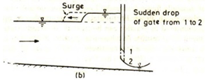
Fig. 11.5. (b) Rapidly varied flow. (Source: Subramanya, 2000)
d) Spatially Varied Flow (SVF)
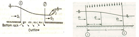
Addition or diminution of water along the course of flow causes non uniform discharge and the resulting flow is known as spatially varied flow (SVF). Hydraulic behaviour of spatially varied flow with increasing discharge (case of drainage channel) is different in certain respects from that of spatially varied flow with decreasing discharge (in case of irrigation channel). Figs. 11.6 (a) shows a case of spatially varied flow with decreasing discharge. Figs. 11.6 (b) shows case of increasing discharge.
(a) (b)
Fig. 11.6. Spatially varied flow: a) decreasing discharge, b) increasing discharge. (Source: Subramanya, 2000).
i) Spatially Varied Flow with Increasing Discharge
In this type of spatially varied flow, an appreciable portion of the energy loss is due to the turbulent mixing of the added water and the water flowing in the channel. In the most cases, this mixing is of relatively high magnitude and uncertainty. Because of the resulting high and uncertain losses, the momentum equation is more convenient than the energy equation in solving spatially varied flow with increasing discharge. From a practical viewpoint, the high energy loss seems to make channels designed for such spatially varied flow hydraulically inefficient, but physical circumstance and economical considerations sometimes make the use of such channels desirable.
ii) Spatially Varied Flow with Decreasing Discharge
Fundamentally, these types of spatially varied flow may be treated as a flow diversion where the diverted water does not affect the energy head. This concept has been verified by both theory and experiments. Therefore, the use of the energy equation is more convenient in solving spatially varied flow with decreasing discharge. The theory of spatially varied flow with decreasing discharge was probably employed first in the design of lateral spillways or side spillway weirs.This type of structure is usually a long notch installed along the side of a channel for the purpose of diverting or spilling excess flow.
The spatially varied flow with decreasing discharge is encountered in the design of irrigation water conveyance system whereas with increasing discharge in design of surface and subsurface drainage systems.
11.4 Sate of Flow
The state of flow in open channels is influenced by viscosity, gravity and inertial forces. The ratio of inertial to viscous force is the Reynolds number.
11.4.1 Effect of Viscosity
In open channel flow may be laminar, transitional or turbulent depending on viscosity in relation to inertial force. If viscous forces are strong in comparison to inertial force, the flow can be laminar otherwise vice versa for turbulentant flow.
The characteristic length-scale for an open channel of width (b) and depth (y), the hydraulic radius (R) = (by/b+2y). As a general rule, open channel flow in laminar, if Reynolds number defined by
Re = ![]() is less than 500.
is less than 500.
Where,
V = Flow Velocity
R = Hydraulic radius
v = Kinematic viscosity.
In open channels the transitional range of Re for practical purpose, is considered between 500 and 2000.The revalue exceeding 2000 is considered as turbulent flow.
In close conduits the flow is i) laminar for Re < 2000, ii) transitional 2000 < Re < 4000 and iii) turbulent Re > 4000.
11.4.2 Effect of Gravity
The effect of gravity is represented by ratio of inertial forces to gravitational forces. This ratio is known as Froude number (Fr), given by
Fr = ![]() (11.1)
(11.1)
V = mean flow velocity,
g = acceleration due to gravity
L = characteristic length (it can be hydraulic depth, y or hydraulic radius, R ).
For the flow to be critical (Fr = 1) i.e.
![]() (11.2)
(11.2)
For sub critical flow (Fr < 1) i.e.
![]() and
and
For super critical flow (Fr > 1) i.e.
![]()
11.5 Seepage in Canals and Field Channels
Seepage loss in unlined canals and farm ditches often range from one-fourth to one-third of the total water diverted. In extremely sandy or gravelly ditches, half the water can be lost through seepage. Reducing seepage by using improved conveyance facilities can increase water available for crop needs, allowing irrigation of additional land, prevent water-logging, increase in channel capacity, reduction in maintenance cost and more importantly enable to use available water sustainably. Especially in the regions of water scarcity, minimising the seepage losses is important.
11.6 Measurement of Seepage in Canal
The most commonly used methods applied for measuring the quantity of water lost due to seepage in a canal section are as follows:
-
Ponding method
-
Inflow-outflow method
-
Seepage meter method
11.6.1 Ponding Method: The ponding method is one of the simplest methods of determining seepage from a canal section. Water is ponded in temporary water-tight dikes constructed in a straight length of canal under investigation. The time rate of drop of the water in the canal level is measured. The dimension of the ponded reach of the canal are measured the seepage computed as volume of water lost from the canal per unit wetted area of canal per unit time and normally is expressed as m3/m2/day.
11.6.2. Inflow-Outflow Method: The inflow-outflow method is based on measuring the rates of water flowing into and out of selected section of canal reach. It is based on water balance approach considering the inflows outflows and losses into account. Canal sections with minimum number of outlets and diversions and no appreciable inflow from higher lands are considered for seepage measurement. Water stage recorders are also used to record the height of flow in the flume as a function of the elapsed time. The seepage is computed as the difference in inflow and outflow per unit wetted area of canal section under consideration.
11.6.3. Seepage Meter Method: The seepage meter is a device for directly measuring the flow between ground water and surface water body such as lake or stream. The seepage meter is a modified form of the constant head permeameter. It is mainly used to determine location of relatively high seepage losses. Seepage meter can be constructed from inexpensive material such as galvanised iron sheet. Seepage meters are suitable when many measurements are needed to characterize groundwater surface water exchange in different sequent of water body.
11.7 Materials for Lining Canals and Field Channels
A large variety of lining materials for seepage loss control from canals and field channels is available for use. Lining of canals or channels offers other advantage such as enhance stability, increasing life, protection from flood in addition to seepage control. The various types of channel lining material commonly used are as follows:
a) Hard surface linings
i) Cement concrete or pre cost concrete,
ii) Stone masonry,
iii) Brick tile or concrete tile
iv) Asphaltic concrete
b) Earth type lining
i) Compacted earth
ii) Soil cement
iii) Bentonite - clay soil mixture
c) Synthetic sheet/film
i) Rubber or synthetic materials
ii) Low density polyethylene sheet
The following points are normally considered for selecting method of lining and materials.
a) Availability and cost of the material at the site or within reach.
b) Labour available for lining at a reasonable cost
c) Degree of water-tightness desired
d) Velocity of flow in the channel
e) Useful life of the lining material
f) Maintenance cost.
References
Subramanya, K. (2000). Flow in Open Channels. Third Reprint Tata McGraw-Hill Publication Company Ltd. New Delhi.
www.nptel.iitm.ac.in/courses/105107059/module1/.../lecture1.pdf.
www.wegc203116.unigraz.at/meted/hydro/basic/Routing/print_Version/03-
streamflow_characteristics.htm.
Suggested Readings
Chow, V. T. (1959). Open-Channel Hydraulics. McGraw-Hill, Book Company Singapore.
James, Larry G. (1988). Principles of Farm Irrigation System Design. John Wiley and Sons, Inc., New York.
Kruse, E. G., Humpheyes, A.S., Pope, E. J. (1980). Farm Water Distribution System. (In Design and Operation of Farm Irrigation Systems, Edited by Jensen, M. E), ASAE Monograph 3, St. Joseph, MI: 395-439.
Michael, A. M. (2010). Irrigation Theory and Practice, Second Edition Vikas Publishing House Pvt. Ltd, Noida, U.P. India: 313-318.
www.ocw.mit.edu/courses/earth...and...to.../ch5.pdf.
Last modified: Thursday, 6 March 2014, 4:44 AM