Site pages
Current course
Participants
General
Module 1: Introduction and Concepts of Remote Sensing
Module 2: Sensors, Platforms and Tracking System
Module 3: Fundamentals of Aerial Photography
Module 4: Digital Image Processing
Module 5: Microwave and Radar System
Module 6: Geographic Information Systems (GIS)
Module 7: Data Models and Structures
Module 8: Map Projections and Datum
Module 9: Operations on Spatial Data
Module 10: Fundamentals of Global Positioning System
Module 11: Applications of Remote Sensing for Eart...
Lesson 15 Radar Systems
Radar is an acronym for radio detection and raging. Radar is an active sensor, which is very sensitive to terrain slope, and its characteristics. Radar can be imaging or non imaging. It transmits microwave signal and receives the reflection or echoes and determines the object distance. It also provides information about the surface features in case of remote sensing application. Radar can be mounted on aircraft or spacecraft. Depending on the working principle, a radar system in remote sensing can be categorized as Real Aperture Radar (RAR) or Side Looking Radar (SLR) and Synthetic Aperture Radar (SAR).
15.1 Real Aperture Radar
Imaging radar is classified into Real Aperture Radar (RAR) and Synthetic Aperture Radar (SAR). Side-Looking Airborne Radar (SLAR) was the first active sensor to produce imagery of the terrain from backscattered microwave radiation. In SLAR, an antenna is mounted underneath the platform to produce a fan beam (which is wide vertically and narrow horizontally) pointed to the side of the platform. The antenna produces a beam of narrow width in the along- track (azimuth) direction, and wide beam in the cross- track (range) direction. A short pulse (energy pulse over a time period on the order of microseconds) is transmitted radially by the antenna, which strikes the ground and backscattered to the antenna. Measuring the total time between transmitting and receiving the signal, the object distance from the platform is measured. The backscattered intensity which depends on the sensor and terrain characteristics is also measured by the radar.
There are few interrelated parameters of a radar system, defines the radar operation. These are
(i) Frequency / wavelength
(ii) Polarization
(iii) Viewing geometry
(iv) Spatial resolution
(i) Frequency / wavelength: The wavelengths used in microwave radar imaging are of in mm to m range. Different names are assigned to microwaves depending on its wavelength, primarily used for security purpose, which is continued for convenience use, given in Table 15.1.
Table 15.1 Wavelength and frequency for radar bands
|
Radar band name |
Wavelength (λ) in cm |
Frequency (ν) in GHz |
|
Ka |
0.75 – 1.18 |
40 – 26.5 |
|
K |
1.19 – 1.67 |
26.5 – 18 |
|
Ku |
1.67 – 2.4 |
18 – 12.5 |
|
X |
2.4 – 3.8 |
12.5 – 8 |
|
C |
3.9 – 7.5 |
8 – 4 |
|
S |
7.5 – 15 |
4 – 2 |
|
L |
15 – 30 |
2 – 1 |
|
P |
30 - 100 |
1 – 0.3 |
(Source: Bhatta, 2008)
Long wavelength microwaves can penetrate more than short wavelength microwaves. Atmospheric effect is observed on shorter wavelength microwaves. The L-band and P-band radar waves have the ability to penetrate the ground surface.
(ii) Polarization: Polarization refers to the orientation of the electric field which may be either vertical (V) or horizontal (H). Radar waves can be transmitted or received at different modes of polarization. There are four combinations of V, H polarized wave transmission and reception as follows:
horizontal (H) transmit & horizontal (H) receive: (HH)
vertical (V) transmit & vertical (V) receive: (VV)
horizontal (H) transmit & vertical (V) receive: (HV)
vertical (V) transmit & horizontal (H) receive: (VH)
HH and VV polarization are said like polarization; HV and VH polarization are said cross-polarization. The strength of backscattered signal for like-polarized wave is greater than cross-polarized wave.
(iii) Viewing geometry: In a radar microwave remote sensing the flight direction is said azimuth direction, and perpendicular to flight direction is said range direction. On the surface, range direction is said ground range direction. The point just below the platform is said nadir. Antenna transmit microwave in the range direction in a fan shape. The nearest point to the nadir of the fan shaped beam is known as near range and farthest point is known as far range. Distance between near range and far range is the swath. Ground range is the horizontal distance measured along the surface from the nadir track to the target.
Incidence angle is the angle between the radar beam and the perpendicular of the surface at a point. Depression angle is the angle of the radar beam to the target (i.e., line of sight from the antenna to the target) measured from a horizontal plane. Look angle is the angle of the radar beam to the target measured from vertical plane (Fig. 15.1).
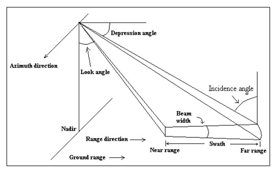
Fig. 15.1. Viewing geometry.
(iv) Spatial resolution: Spatial resolution is one of the most important parameter in radar imaging. There are two types of resolution associated with radar imaging: a. range resolution and b. azimuth resolution.
a. Range resolution: To distinguish two objects in a radar image in the range direction, it is necessary to reach the backscatter from the two objects separately. In the Fig. 15.2, a microwave of pulse length L is transmitted, which is backscattered from objects A and B, situated at a distance d in the slant range direction and R in the ground range direction.
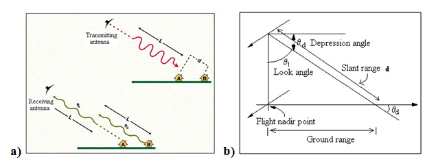
Fig. 15.2. Dependence of spatial resolution on pulse length.
(Source: earth.esa.int/applications/data_util/SARDOCS/spaceborne/ Radar_Courses/Radar_Course_II/real_aperture_radar_range_resolution.htm)
So, the objects A and B can be discriminated in the imagery if the slant range distance between A and B is greater than half of the pulse length. If the front of the backscattered wave from B touches the rear of the backscattered from A (Fig. 15.2(a)). Therefore, they cannot be resolved in the imagery. If t be the pulse duration, c be the velocity of microwave, then the ground range resolution (R) can be expressed as:
R = (ct)/(2cosθd) (15.1)
where θd is the depression angle and t is the time in µsec.
Further, this should be noted that the ground range resolution can be increased by increasing the depression angle and decreasing the pulse length. But depression angle increases, cosθd decreases, which will in turn increase the ground range.
Example 15.1: A SLAR system transmits pulse over duration of 0.2 µsec at a depression angle of 23o. What would be the ground range resolution?
Solution:
From equation (1), ground range resolution R
R = (ct)/2cosθd
= ((3 x 10⁸) (0.1 x 10⁻⁶))/(2 x cos23o ) m. sec-1.sec
= 16.3 m
b. Azimuth resolution: The spatial resolution in the azimuth direction is defined by the signal beam width (β). As the beam is fans on the ground, thus the spatial resolution in the azimuth direction varies in the ground range direction. In the Fig. 15.3, at the point A, three points are resolved spatially, where as the points in point B (spaced equally as at the point A) are not resolved. That means at near range the azimuth resolution is higher than far range. The azimuth resolution (r) can be expressed as:
r = βP (15.2)
where, P is the slant range distance.
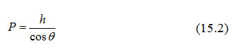
h is the altitude of platform, θ is look angle,
or, 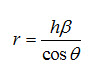
If D be antenna length, λ be the operating wavelength, then antenna beam width (β)

Thus we have azimuth resolution (r)
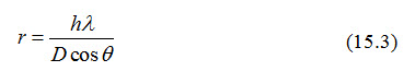
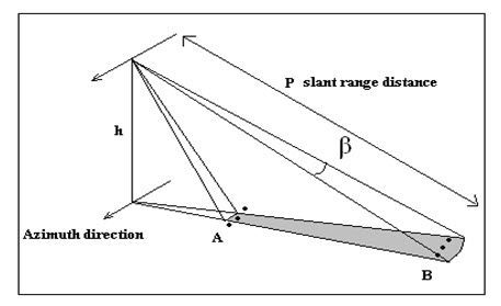
Fig. 15.3. Azimuth resolution.
To increase resolution by decreasing wavelength leads to cloud and atmospheric attenuation. For a particular wavelength, the azimuth resolution can be increased by decreasing the platform altitude, which is nearly constant for space borne satellites. Another way of increasing azimuth resolution is by increasing the antenna length. But increasing the antenna length physically at a big scale is impractical. For, an example, a SLAR system operating in 3 cm wavelength, having altitude 705 km. and 30o look angle. To obtain 30 m resolution, the antenna length should be 814 m. which is impractical. In case of airborne radar antenna length is usually 1-2 m, and for space borne 10-15m.
So, the resolution can be increased by increasing the antenna length virtually, which is known as synthetic aperture radar (SAR).
15.2 Synthetic Aperture Radar
The deficiency of real aperture radar (RAR) is overcome in synthetic aperture radar (SAR) systems. In SAR systems a short physical antenna is used as in RAR, which is synthesized so that it can act as a very long antenna. The result of this mode of operation is a very narrow effective antenna beamwidth, even at far ranges, without requiring physically long antenna or a short operating wavelength, which increases the azimuth resolution subsequently.
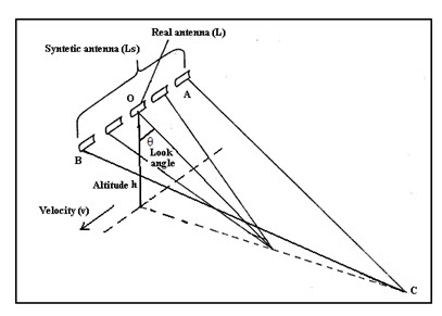
Fig. 15.4. Concepts of real antenna positions forming a synthetic aperture.
The concept of SAR operation is shown in Fig 15.4. The real antenna length (L) is increased virtually at a synthetic aperture antenna length (Ls). This results in essentially constant azimuth resolution irrespective of range. Through this process, the antenna length can be made several km. The antenna starts to transmit signal at position A and continues till B, thus backscatter from target C can be recorded during this entire time of signal transmission. Objects at far range, where the beam width is wider illuminated for longer time than the objects of near range where the beam width is narrower; thus it maintains constant range resolution. Due to relative motion of platform and object, a Doppler shift is observed in the signal. From the path A – O, the frequency of the signal will increase, at the points nearer to the point O, the frequency shift will be very less, and from point O – B the frequency will be decrease. This error can be processed accounting the Doppler shift.
Example 15.2: In the Fig. 15.4., a space borne radar operating at wavelength 3 cm, at an altitude 700 km. If the look angle is 30o and synthetic aperture length is 1 km, what would be the azimuth resolution of the data obtained?
Solution:
Using the equation (2), ground range resolution R
r = hλ / Lcosθ
= ((700 x 103) (3 x 10⁻²))/(1 x103 x cos30o ) m.
= 24 m.
15.3 Scatterometer
Scatterometer measures the power of the backscatter reflected from the surface of the earth. The amount of backscatter depends on the properties and characteristics of the surface of the earth. A microwave scatterometer may be a space borne sensor to measure the two dimensional velocity vectors of the sea wind, as well as ground based sensors to measure the surface backscattering as well as volume scattering, such as rain radar. It is calibrated to measure accurately scattering the coefficient σo. The principle of a scatterometer may be pulse type or continuous wave type. A pulse type scatterometer transmits signal, the backscatter intensity and the time delay is measured, gives the information and location of the target.
The scattering coefficient σo is related to other instrument as follows

where,
Go= the maximum gain of the antenna
λ= wavelength
R= Range
Pt= transmit power
Pr= received power
Aw= weighted area
g (θ, Φ)= normalized antenna gain (radiation pattern) such that the antenna gain
G= Gog(θ, Φ)
Ai= area of illumination
SESAT-A Scatterometer (SASS) was launched in 1978 is one of the typical scatterometer. SASS uses four beam antennas- two on both the sides of the sub-satellite track to receive the backscattering in subdivided cells through a Doppler filter. Two antennas on each side are aligned so that they are pointed 45o and 135o relative to the spacecraft flight direction. Thus, the footprint of the four antenna beam produce an ‘X’ shaped illumination pattern and on the earth (Fig. 15.5.). Thus, ant surface location is viewed by both the forward and aft antenna, near orthogonally (separated by approximately 90o).
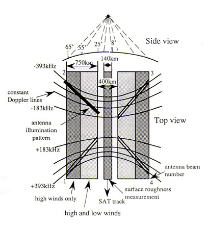
Fig. 15.5. Seasat SASS fan-beam coverage.
(Source: stlab.iis.u-tokyo.ac.jp/~wataru/lecture/rsgis/rsnote/cp4/4-9-1.gif)
Keywords: Real Aperture radar (RAR), Synthetic Aperture Radar (SAR), Side-Looking Airborne Radar (SLAR), Range resolution, Azimuth resolution, Polarization, Scatterometer.
References
Bhatta, B., 2008, Remote sensing and GIS, Oxford University Press, New Delhi, pp. 168.
earth.esa.int/applications/data_util/SARDOCS/spaceborne/Radar_Courses/Radar_Course_II/real_aperture_radar_range_resolution.htm; Dec. 20, 2012.
stlab.iis.u-tokyo.ac.jp/~wataru/lecture/rsgis/rsnote/cp4/4-9-1.gif
Suggested Reading
Joseph, G., 2005, Fundamentals of Remote Sensing, Second Edition, Universities Press (India) Pvt. Ltd., pp. 213-259.
Lillesand, T. M., Kiefer, R. W., 2002, Remote sensing and image interpretation, Fourth Edition, pp. 616-700.
stlab.iis.u-tokyo.ac.jp/~wataru/lecture/rsgis/rsnote/contents.htm
www.radartutorial.eu/20.airborne/ab07.en.html
Last modified: Monday, 27 January 2014, 4:38 AM