Site pages
Current course
Participants
General
Module 1: Introduction and Concepts of Remote Sensing
Module 2: Sensors, Platforms and Tracking System
Module 3: Fundamentals of Aerial Photography
Module 4: Digital Image Processing
Module 5: Microwave and Radar System
Module 6: Geographic Information Systems (GIS)
Module 7: Data Models and Structures
Module 8: Map Projections and Datum
Module 9: Operations on Spatial Data
Module 10: Fundamentals of Global Positioning System
Module 11: Applications of Remote Sensing for Eart...
Lesson 27 GPS
27.1 Components of GPS
GPS is a Satellite Navigation System. It stands for Global Positioning System. GPS is funded by and controlled by the U. S. Department of Defense (DOD). While there are many thousands of civil users of GPS world-wide, the system was designed for and is operated by the U. S. military. GPS provides specially coded satellite signals that can be processed in a GPS receiver, enabling the receiver to compute position, velocity and time. Four GPS satellite signals are used to compute positions in three dimensions and the time offset in the receiver clock. ( http://www.colorado.edu/geography/gcraft/notes/gps/gps.html#SVData; November 30.2012).
Here we will mostly focus on the NAVSTAR, the mostly available and used system. GPS consists of mainly three segments, these are
Space segment (the satellites )
Control segment (the ground stations)
User segment (user and their GPS receiver)
27.1.1 Space segment
The space segment (SS) is composed of the orbiting GPS satellites, or Space Vehicles (SV). It consists of 24 satellites (21 active plus 3 operating spares), eight each in three circular orbital planes. The satellites are manufactured by Rockwell International, which are launched into space by rockets, from Cape Canaveral, Florida. They are about the size of a car, and weigh about 19,000lbs. This was modified to six planes with four satellites each. The orbital planes are centered on the Earth. The six planes have approximately 55° inclination and are separated by 60° right ascension of the ascending node. This constellation ensures that there will always be at least 4 satellites above the horizon at any location on the surface of the globe.
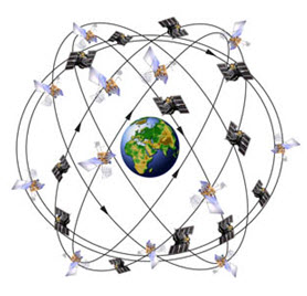
Fig. 27.1. Space segment. (Source: http://www.aboutcivil.org/components-of-gps-working-mechanism.html; November 05, 2012)
The space segment transmits a variety of information particularly time and satellite position information. Satellites are orbiting at an altitude of approximately 20, 200 kilometers. The satellites travel at a speed of 7000 miles/h, which allows them circle the earth once in every 12 hours. They are powered by solar energy and are built to last about 10 years. The satellites continuously orient themselves to ensure that their solar panels stay pointed towards the sun, and their antennas point toward the earth. Each satellite carries 4 atomic clocks.
The first GPS satellites are launched into space in 1978. A full consolidation of 24 satellites was achieved in 1994. The satellites are geostationary and non-geostationary. At any given time there are 12 satellites at either side of the hemispheres.
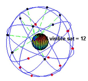
Fig. 27.2. GPS constellation. (Source: http://www.aboutcivil.org/components-of-gps-working-mechanism.html ;November 05, 2012)
Each satellite consists of three high precision atomic clocks and is constantly transmitting radio signals using its own unique identification code. Each satellite transmits low power radio signals on several frequencies (designed L1, L2 etc.). GPS receivers “listen” on L1 frequency of 1575.42 MHz and L2 frequency of 1227.60 MHz. Civilian GPS receivers can use only the L1 signals. These signals can pass through clouds, grass, plastics, but not pass though solid objects such as buildings and mountains. Each signal consists of two “pseudo random” signals, the protected (P) code and course acquisition (CA) code. C/A is available for civilians and (P) used by US military receivers.
The main purpose of these signals is to calculate the travel time from satellite to the GPS receiver on the earth. The travel time is called time of arrival. The travel time multiplied by speed of light equals the satellite range (distance from the satellite to the GPS receiver). (Bhatta, 2008).
27.1.2 Control Segment
The control segment is composed of
A master control station (MCS),
An alternate master control station,
Four dedicated ground antennas and
Six dedicated monitor stations
The MCS can also access U.S. Air Force Satellite Control Network (AFSCN) ground antennas (for additional command and control capability) and NGA (National Geospatial-Intelligence Agency) monitor stations.

Fig. 27.3. Control Segment. (Source: http://www.aboutcivil.org/components-of-gps-working-mechanism.html;November 10, 2012)
The flight paths of the satellites are tracked by dedicated U.S. Air Force monitoring stations in Hawaii, Kwajalein, Ascension Island, Diego Garcia, Colorado Springs, Colorado and Cape Canaveral, along with shared NGA monitor stations operated in England, Argentina, Ecuador, Bahrain, Australia and Washington DC.
Then 2 SOPS contacts each GPS satellite regularly with a navigational update using dedicated or shared (AFSCN) ground antennas (GPS dedicated ground antennas are located at Kwajalein, Ascension Island, Diego Garcia, and Cape Canaveral).
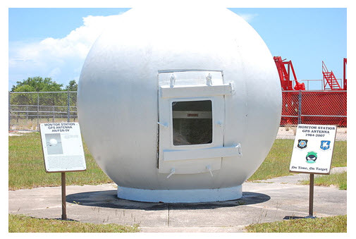
Fig. 27.4. Ground monitor station used from 1984 to 2007, on display at the Air Force Space & Missile Museum.
(Source: http://en.wikipedia.org/wiki/Global_Positioning_System; November 15, 2012)

Fig. 27.5. GPS Control.
(Source: http://www.colorado.edu/geography/gcraft/notes/gps/gps_f.html; December 1, 2012)
These updates synchronize the atomic clocks on board the satellites to within a few nanoseconds of each other, and adjust the ephemeris of each satellite's internal orbital model. The updates are created by a Kalman filter that uses inputs from the ground monitoring stations, space weather information, and various other inputs.
Satellite maneuvers are not precise by GPS standards. So to change the orbit of a satellite, the satellite must be marked unhealthy, so receivers will not use it in their calculation. Then the maneuver can be carried out, and the resulting orbit tracked from the ground. Then the new ephemeris is uploaded and the satellite marked healthy again.
The Operation Control Segment (OCS) currently serves as the control segment of record. It provides the operational capability that supports global GPS users and keeps the GPS system operational and performing within specification. OCS successfully replaced the legacy 1970’s-era mainframe computer at Schriever Air Force Base in September 2007. After installation, the system helped enable upgrades and provide a foundation for a new security architecture that supported the U.S. armed forces. OCS will continue to be the ground control system of record until the new segment, Next Generation GPS Operation Control System (OCX), is fully developed and functional.
The new capabilities provided by OCX will be the cornerstone for revolutionizing GPS’s mission capabilities, and enabling Air Force Space Command to greatly enhance GPS operational services to U.S. combat forces, civil partners and myriad of domestic and international users.
The GPS OCX program also will reduce cost, schedule and technical risk. It is designed to provide 50% sustainment cost savings through efficient software architecture and Performance-Based Logistics. In addition, GPS OCX expected to cost millions less than the cost to upgrade OCS while providing four times the capability.
The GPS OCX program represents a critical part of GPS modernization and provides significant information assurance improvements over the current GPS OCS program.
OCX will have the ability to control and manage GPS legacy satellites as well as the next generation of GPS III satellites, while enabling the full array of military signals.
Built on a flexible architecture that can rapidly adapt to the changing needs of today’s and future GPS users allowing immediate access to GPS data and constellations status through secure, accurate and reliable information.
Empowers the warfighter with more secure, actionable and predictive information to enhance situational awareness.
Enables new modernized signals (L1C, L2C, and L5) and has M-code capability, which the legacy system is unable to do.
Provides significant information assurance improvements over the current program including detecting and preventing cyber-attacks, while isolating, containing and operating during such attacks.
Supports higher volume near real-time command and control capabilities
On September 14, 201, the U.S. Air Force announced the completion of GPS OCX Preliminary Design Review and confirmed that the OCX program is ready for the next phase of development.
The GPS OCX program has achieved major milestones and is on track to support the GPS IIIA launch in May 2014.
(http://en.wikipedia.org/wiki/Global_Positioning_System; October 15.2012)
27.1.3 User segment
The user segment just consists of the user and his GPS receiver. It is composed of hundreds of thousands of U.S. and allied military users of the secure GPS Precise Positioning Service, and tens of millions of civil, commercial and scientific users of the Standard Positioning Service. In general, GPS receivers are composed of an antenna (Internal or external), tuned to the frequencies transmitted by the satellites, receiver-processors, and a highly stable clock (often a crystal oscillator). Generally, they also include a display for providing location and speed information to the user. A receiver is often described by its No. of channels: this signifies signals’ from how many satellites it can process simultaneously. Originally limited to 4 or 5, this has progressively increased over the years so that, as of year 2007, receivers typically have between 12 and 20 channels. (Bhatta, 2008)
GPS receivers may include an input for differential corrections, using the RTCM SC-104 format. This is typically in the form of an RS-232 port at 4,800 bit/s speed. Data is actually sent at a much lower rate, which limits the accuracy of the signal sent using RTCM. Receivers with internal DGPS receivers can outperform those using external RTCM data. As of 2006, even low-cost units commonly include Wide Area Augmentation System (WAAS) receivers.
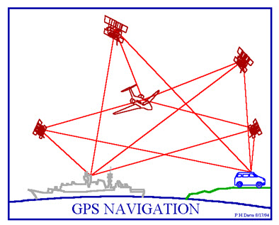
Fig. 27.6. GPS Navigation.
(Source: http://www.colorado.edu/geography/gcraft/notes/gps/gps_f.html; December 1, 2012)
Many GPS receivers can relay position data to a PC or other device using the NMEA 0183 protocol. Although this protocol is officially defined by the National Marine Electronics Association (NMEA), references to this protocol have been compiled from public records, allowing open source tools like gpsd to read the protocol without violating intellectual property laws. Other proprietary protocols exist as well, such as the SiRF and MTK protocols. Receivers can interface with other devices using methods including a serial connection, USB, or Bluetooth. http://en.wikipedia.org/wiki/Global_Positioning_System; October 15.2012.
27.2 Working Principles
When the GPS receiver starts its job, it should have information about where the satellites are and how far away they are.
Let us first look at how the GPS receiver knows where the satellites are located in space. This GPS receiver picks up two kinds of corded information from the satellites, almanac and ephemeris. Almanac data is a course orbital model for all satellites. Each satellite broadcasts almanac data for all satellites. This almanac data is not very precise and consider valid for unto several hours. This data is continuously transmitted and stored in the memory of GPS receiver so that it knows the orbits of satellites and where each satellite is supposed to be. The almanac data is periodically updated with new information as the satellite move around.
Ephemeris data by comparison is a very precise orbital and clock correction for each satellites and is necessary for precise positioning any satellite can travel slightly out of orbit, so the ground monitor station keep track of the satellite orbits altitude, location and speed. The ground monitor stations send the monitored orbital data to the master control station, which in turn sends corrected orbital data and clock corrections up to the satellites. This corrected and exact positioned data is called the ephemeris data, which is transmitted as coded information to the GPS receiver. Each satellite broadcasts only its own ephemeris data. Subsets of ephemeris data are broadcast by each satellite continuously, which remains valid for the orbit for the few minutes.
The unit stored data about where the satellites are located at any given time. This data is called the almanac. On the ground, all GPS receivers have an almanac programmed into their computers that tells them where in the sky each satellite is moment by moment. This data helps the receiver to track the satellite faster. Ephemeris data is required to know the exact positions of each visible satellite and clock error for the precise calculation of the receiver location.
Therefore, having received the almanac and ephemeris data, the GPS receiver knows the precise positions of the satellite at all times. (Bhatta, 2008)
27.3 Timing and Ranging
Even though the GPS receiver knows the precise location of the satellite in space, it still needs to know how far away the satellites are (the distance), so it can determine its position on earth. These is a simple formula that tells the receive how far it is form each satellite.
The distance (from us) from a given satellite objects equals the velocity of the transmitted signal multiplied by the time taken by the signal to reach us ().
We recollect how in our childhood we tried to find out how far a thunderstorm was from us. When we saw a lightning flash, we counted the number of seconds until we heard the thunder. The longer the count, the farther away the storm was. GPS works on the same principle called time of arrival. We would have noticed that during a thunderstorm, we heard the sound sometime after we saw the light. The reason is that sound waves travel much slower than light waves. We can estimate our distance to the storm by measuring the delay between the time that we see the thunder and the time that we hear it. Multiplying this time delay by the speed of sound gives us our distance to the storm (assuming that the light reaches us almost instantaneously compared to sound). Sound travels about 344 m (1,130 ft) per second in air. So if it takes 2s between the times that we see the lightning and the time we hear it, our distance to the storm is 2 x 344 = 688 m. We calculate the distance to an object by measuring the time that it takes for its signal to reach us.
Using the same basic formula to determine distance, the receiver already knows the velocity. It is the speed of a radio wave-186,000 miles (3 x 10⁸ m) per second (the speed of light), less any delay as the signal travels through the earth's atmosphere.
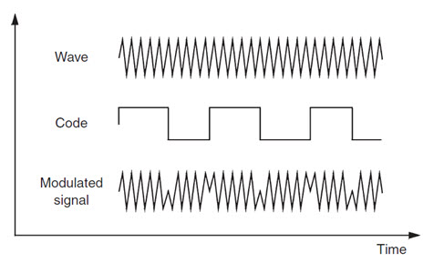
Fig. 27.7. Modulation of carrier wave. (Source: Konecny, 2003)
Now the GPS receiver needs to determine the time part of the formula. The answer lies in the coded signals the satellites transmit. The transmitted code is called 'Pseudo Random Code' (PRC) because it looks like a noise signal. The PRC is a fundamental part of GPS. Physically, it is just a very complicated digital code. The signal is so complicated that it almost looks like random electrical noise and hence the name is 'pseudo-random’. There are several good reasons for its complexity: First, the complex pattern helps make sure that the receiver does not accidentally sync up to some other signal. Since each satellite has its own unique PRC, this complexity also guarantees that the receiver would not accidentally pick up the signal of another satellite. However, the reason that is crucial to make the GPS economical is that the codes make it possible to use ‘information theory’ to 'amplify' the GPS signal. Because of this reason GPS receivers do not require big satellite dishes to receive the GPS signals.
When a satellite generates the FRC the GPS receiver simultaneously generates the same code and tries to match it up to the satellite’s code. The receiver then compares the two codes to determine how much it needs to delay (or shift) its code to match the satellite code. This delay time (shift) is multiplied by the speed of light to get the distance.
Our GPS receiver clock does not keep the time as precisely as the satellite clock. Putting an atomic clock in our GPS receiver would make it much larger and far more expensive. Therefore, each distance measurement needs to be corrected to account for the GPS receiver's internal clock error. For this reason, the range measurement is referred to as a 'pseudo-range'. To determine position using pseudo-range data, a minimum of four satellites must be tracked and the four fixes must be recomputed until the clerk error disappears.
Note: The delay of time can be understood by the following example:
Let us assume that our friend at the end of a large field repeatedly shouts numbers from 1 to 10 at the rate of one count per second (10 s for a full cycle of 1 to 10 counts). Let us also assume that we do the exact same thing, synchronized with him, at the other end of the field. Synchronization between us and him could have been achieved by both starting at an exact second and observing our watches to count 1 number per second. We assume that both have very accurate watches. Because of the sound travel time, we hear the number patterns of our friend with a delay relative to our patterns. If we hear the friend's count with a delay of one count relative to ours, then our friend must be 344 m away from us (344 m/s, the velocity of sound = 344 m x 1 s). This is because the counts are 1 s apart.

Fig. 27.8. Components of GPS.
(Source: Lecture 16: Global Positioning System.pdf)
27.4 How GPS Works
Calculating Location
The basis of GPS is ‘triangulation’ from satellites also called trilateration. To ‘triangulate’, a GPS receiver measures distance using the travel time of radio signals. To measure travel time, GPS needs very accurate timing, which is achieved through some tricks. Along with distance, we need to know exactly where the satellites are in space. (Bhatta, 2008)
Trilateration
Trilateration is a process that uses distance from at least three known locations to determine position. GPS receivers calculate the position of objects in two dimensional or three dimensional spaces using a mathematical process called trilaterlation. Trilateration can be either two dimensional or three dimensional. Let us examine how 2-D and 3-D trilateration work.
http://www.roseindia.net/technology/gps/what-is-trilateration.html; November 30.2012.
2-D Trilateration
The concept of trilateration is easy to understand through an example. Imagine that you are driving through an unfamiliar country and that you are lost. A road sign indicates that you are 500 km from city A. But this is not of much help, as you could be anywhere in a circle of 500 km radius from the city A. A person you stop by to ask for directions then volunteers that you are 450 km from city B. Now you are in a better position to locate yourself- you are at one of the two intersecting points of the two circles surrounding city A and city B. Now if you could also get your distance from another place say city C, you can locate yourself very precisely, as these three circles can intersect each other at just one point. This is the principle behind 2D trilateration.
http://www.roseindia.net/technology/gps/what-is-trilateration.html; November 30.2012.
3-D Trilateration
The fundamental principles are the same for 2D and 3D trilateration, but in 3D trilateration we are dealing with spheres instead of circles. It is a little tricky to visualize. Here, we have to imagine the radii from the previous example going in all directions, that is in three dimensional space, thus forming spheres around the predefined points. Therefore the location of an object has to be defined with reference to the intersecting point of three spheres.
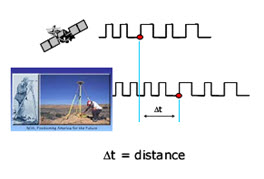
Fig. 27.9. Travel time determination from shifting of code.
(Source: Lecture 16: Global Positioning System.pdf)
GPS use clocks and trilateration to determine position. The satellite vehicles (SV) and receiving units both contain highly accurate clocks. Part of the information that the SV transmits is a time stamp. When a GPS unit receives the transmission, it compares the time stamp from the satellite to the time it reached the receiver. The difference between the two is multiplied by the speed of the transmission signal p the distance that the signal traveled.
http://www.roseindia.net/technology/gps/what-is-trilateration.html;November 30.2012.
Suppose we measure our distance from a satellite and find it to be 20,000 km, knowing that we are 20,000 km from a particular satellite narrows down all the possible locations we could be in the whole universe to the surface of a sphere that is centered on this satellite and has a radius of 20,000 km.
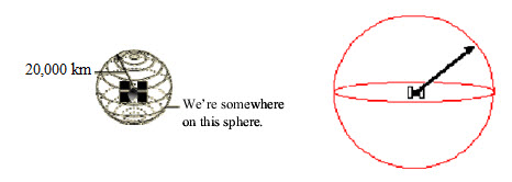
Fig. 27.10. Distance from a single satellite.
(Source: Lecture 16: Global Positioning System.pdf 2nd Principles of GPS by Dana m. Sommer.pdf)
Next, let us say we measure our distance to a second satellite and find out that it is 21,000 km away. This conveys that we are not only on the first sphere but we are also on a sphere that is 21,000 km from the second satellite. Or in other words, we are somewhere on the circle where these two spheres intersecting.
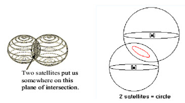
Fig. 27.11. Distance from two satellites.
(Source: Lecture 16: Global Positioning System.pdf, 2nd Principles of GPS by Dana m. Sommer. pdf)
If we then make a measurement from a third satellite and find that we are 22,000 km from that one, which narrows our position down even further, to the two points where the 22,000 km sphere cuts through the circle that is the intersection of the first two spheres. So by ranging from three satellites we can narrow our position to just two points in space.
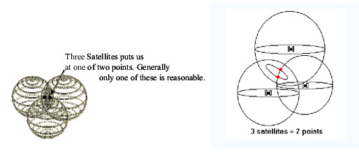
Fig. 27.12. Location from three satellites.
(Source: Lecture 16: Global Positioning System.pdf 2nd Principles of GPS by Dana m. Sommer.pdf)
Even though there are two possible positions, they differ greatly in latitude/longitude position and Altitude. However, by adding a fourth satellite, the receiver can determine our three-dimensional position (latitude, longitude, altitude). Let us say our distance from a fourth satellite is 21,000 km. We now have a fourth sphere intersecting the first three spheres at one common point. But usually one of the two points (in case of three satellite references) is a ridiculous answer (either too far from the earth or moving at an impossible velocity) and can be rejected without a measurement, though, a fourth satellite gives us more accurate positional information. (Bhatta, 2008).
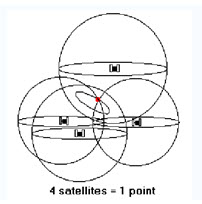
Fig. 27.13. Location from 4 satellites.
(Source: Lecture 16: Global Positioning System.pdf)
A fourth measurement does come in for another reason, to achieve or measure accurate time in the GPS receiver.
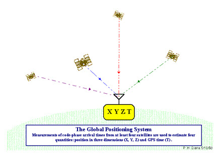
Fig. 27.14. Measurements of arrival times from four satellites.
(Source: http://www.colorado.edu/geography/gcraft/notes/gps/gpsf.html; December 1, 2012)
On the satellite side, the timing is almost perfect because they have incredibly precise atomic clocks on board, but the receiver does not have precise atomic clock. But both the satellite and the receiver need to be able to precisely synchronize their PRCs to make the system work. The designers of GPS came up with a brilliant little trick that lets us get by with much less accurate clocks in our receivers. This trick is one of the key elements of GPS and as an added side benefit, it means that even GPS receiver is essentially an atomic-accuracy clock. (Bhatta, 2008)
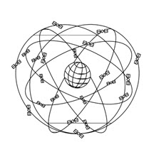
Fig. 27.15. Global GPS satellite configuration. (Source: Konecny, 2003,)
If our receiver’s clocks were perfect, then all the satellite ranges would intersect at a single point (which is our position). But with imperfect clocks, a fourth measurement, done as a cross-check that will not intersect with the first three. Thus the receiver's computer determines the discrepancy in measurements.
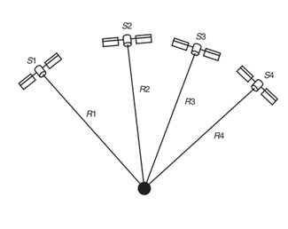
Fig. 27.16. Shows the determination of the position from the four distance measurements, R1, R2, R3 and R4. (Source: Konecny, 2003)
Then the receiver looks for a correction factor that it can deduct from all its timing measurements that would cause them all to intersect at a single point. That correction brings the receiver's clock back into synchronize and we have acquired atomic accuracy time right in the palm of our hand. Once that correction is made, it applies to all the rest of its measurements and now we have obtained precise positioning. One consequence of this principle is that, it is necessary for any decent GPS receiver to acquire at least four channels so that it can make the four measurements simultaneously. Since the receiver must solve for its position (x0, y0, z0) and the clock error (t) (in terms of time-duration), four satellites are required to solve the receiver's position using the following four equations:
where (x1, y1, z1), (x2, y2, z2), (x3, y3, z3), and (x4, y4, z4) stand for the locations of satellites, which are known and R1, R2 R3, and R4 are the distances of satellites from the receiver position (Fig. 7.9), which are derived, c is the velocity of signal (or light). Hence solving the four equations for four unknowns x0, y0, z0 and t, at least four navigation satellites are necessary. The GPS receiver routinely solves these simultaneous equations using dedicated software installed within it. The coordinates (x0, y0, z0) are calculated according to the World Geodetic System (WGS 1984) coordinates system. (Bhatta, 2008).
Note: A GPS user is likely to have experienced a wrong set-up in his GPS receiver relative to the map he uses. It is essential that the GPS receiver be set up to conform to the map. In particular, the coordinate system and its datum need to be the same. The GPS calculates the position based on World Geodetic System 1984 (WGS 84) spheroid and datum. However, users may encounter maps that use other datums and spheroids, The details for each specific map can be found in the margin information on the map, and must be entered correctly into the GPS receiver if an accurate relationship between the GPS receiver and the map is to be assured.
Keywords: Space segment, Control Segment, User segment, Wide Area Augmentation System (WAAS) , GPS, NAVSTAR, OCS, SV, CA code, WGS
References
Konecny, G. 2003. Geoinformation, Taylor & Francis, London, pp.225-230.
Harvey, F. 2008. A Primer of GIS, The Guilford Press, New York, pp.144-151.
McNamara, J. 2004. GPS for Dummies, Wiley Publishing, NJ, pp. 47-117.
Bhatta, B. 2008. Remote Sensing and GIS, Oxford University Press, New Delhi, pp.192-204
http://www.roseindia.net/technology/gps/what-is-trilateration.html; November 30.2012.
PRINCIPLES OF GPS By Dana M. Sommer.pdf
http://www.aboutcivil.org/components-of-gps-working-mechanism.html; November 5.2012
http://www.colorado.edu/geography/gcraft/notes/gps/gps.html#SVData; November 30.2012
http://support.radioshack.com/support_tutorials/gps/gps_parts.htm; November 30.2012
http://en.wikipedia.org/wiki/Global_Positioning_System; October 15.2012.
Lecture 16: Global Positioning System.pdf
Suggested Reading
http://www8.garmin.com/aboutGPS/; November 30.2012
http://www.fas.org/spp/military/program/nav/gps.htm; December 1.2012
http://www.schriever.af.mil/news/story.asp?id=123260251; November 30.2012
Last modified: Saturday, 1 February 2014, 6:00 AM