Site pages
Current course
Participants
General
Module 1. Micro-irrigation
Module 2. Drip Irrigation System Design and Instal...
Module 3. Sprinkler Irrigation
Module 4. Fertigation System
Module 5. Quality Assurance & Economic Analysis
Module 6. Automation of Micro Irrigation System
Module 7. Greenhouse/Polyhouse Technology
Lesson 26. Components of Automation System
26.1 Introduction
Automation in micro-irrigation system is typically achieved by a centralized decision making control device supported with a set of hardware (control valves, relays etc.) to carry out irrigation commands and sensors to input environmental measurements for making irrigation decision.
The basic structure and components of a relatively comprehensive irrigation control system are shown in Figure 26.1.
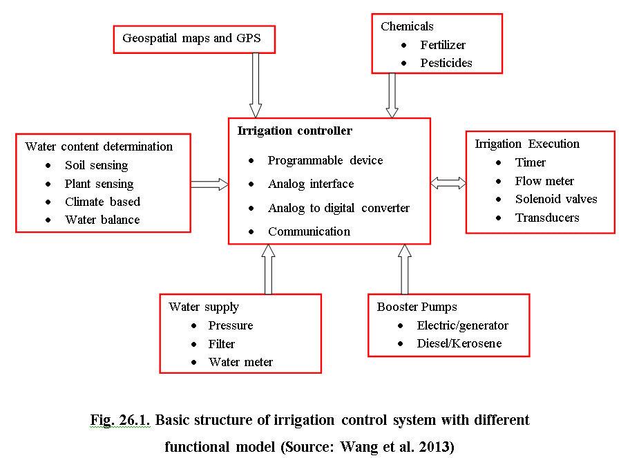
For automation of irrigation, the irrigation controller is used. The irrigation controller is an electronic device to store and execute irrigation scheduling program based on soil/plant water content and using criteria of when and how much water to supply. The following are the decision making steps to execute irrigation.
i) Geospatial data are provided to the controller to generate site specific water assessment or demand for water to irrigate field crops.
ii) Assessment of water demand using a) soil moisture/plant water status sensors in-situ or remotely located, b) meteorological based soil-water balance estimation and c) calendar based soil-water balance.
iii) Direct continuous communication between these sensors and irrigation controllers is essential, which can be achieved by directly connecting the sensors output to the analog interface panel for wired system or through wireless transmitters/receivers.
iv) If irrigation is to be given after knowing soil-water status, the irrigation is given using a pump attached with source of water and network of pressurized irrigation pipe lines. In case of additional pressure requirement the booster pump can be operated electrically or fossil fuel.
v) The set of control and monitoring devices are deployed to execute irrigation command to complete the irrigation. Solenoid valves are used to turn on/off water flow with the amount of water monitored by water meter. Sometimes timer is used to apply water for set time.
vi) Fertigation or chemigation is important process in micro-irrigation. This may be with or without automation.
vii) Sometimes filters cleaning and backwashing are automated/manually operated. The last step involves system monitoring to ensure system maintenance. This is accomplished by supervisory control and remote monitoring to ensure optimal irrigation.
26.2 Automation Equipments and Their Application
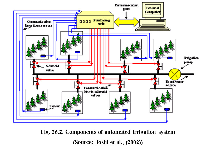
The devices used for automation of micro-irrigation (MI) system are: controller, control valves, metering pumps, flow transducers, sequencers sensors, master relay etc. The brief description of these hardware equipments are presented in this section. Fig. 26.2 shows different components of computer controlled automated irrigation system developed at IIT Kharagpur, India.
26.2.1 Controller
The PLC (Programmable Logic Controllers) is used extensively for various industrial applications including irrigation. These are available for inputs/outputs varying from 6 to 512. The analog input/output modules enable interfacing of base unit of PLC with many sensors, transducers and output devices. These systems can be programmed to issue command for operation of solenoid valves, pumps, booster, fertilizer injectors, backwashing of filters etc. according to irrigation cycle (Dhingra & Kumar, 2001). Micro-processor, personal computers, laptops, palmtops are also used as controllers.
The controller is heart of the automation, which co-ordinates operation of the entire system. The controller is programmed to run various zones of an area for their required duration. In some cases moisture sensors is used with it which gives feed back to the controller about field moisture level.
The controller has in-built 24-hr clock. There is an option to have different irrigation schedule for different days of the week. These are mostly multistation controller i.e. they can control 4/6/8/12 and even more number of solenoid valves are connected through them. Other facilities available with the controllers are multi programme facility to suit different weather conditions, weekly/fortnightly calendar or skip days interval option and option to connect moisture sensors, temperature sensor, or other sensors having analog output (Joshi 2001). The different types of controller are: cyclic controller, stand alone battery operated controller, light commercial controller, coded signal controller and satellite based computerized control system. The cyclic controller can be used for one station where as satellite based controller can be used for as maximum as 999 stations.
26.2.2 Control Valves
Control valves are activated electrically, hydraulically or pneumatically and used to switch on or off water supply, filter flushing, mains and laterals, sequence water from one field or segment to another.
a) Solenoid valve: Controllers are connected electrically operated valves (solenoid valve). These valves are fitted in place of manual gate valve in an automatic system. One valve controls one section. As soon as the signal is received from the controller the solenoid gets activated and valve is turned on which allows passing of water through it. After the signal is stopped the valve shuts off. These are normally two way open and close valves and operate on 24 volt DC or 220 volt AC motor.
b) Hydraulic valves: These valves are operated on hydraulic pressure. The operation of a hydraulic valve depends on the type of valve and whether it is NC (Normally closed) or NO (Normally open) in principle.
A command can be transmitted to these hydraulic valves by means of control tubes and solenoid coil. These solenoid coils are mounted on the main line and connected to the valve by control tubing.
c) Solenoid coil: Solenoid coil is used to translate electric pulses into hydraulic pulses which enable opening and closing of specific hydraulic valve. These solenoid coils require 24V AC input for its operation. Solenoid coils mounted on the valves are connected to controller electrically. The size of the cable is the function of the distance between solenoid valve and the controller. The solenoid coil has a metal plunger inside the electromagnetic coil. The coil gets actuated after receiving required voltage. It pulls up the plunger and water passes from the lower orifice port to control tubing towards the hydraulic valve. When operation time is over, the controller stops sending signals to the solenoid coil to deactuate. Thus the plunger again seals the orifice port to close.
d) Automatic metering valves: These valves are used in volume based irrigation system. The volume of water required for the irrigation can be adjusted in these automatic metering valves. It shuts itself off after a preset quantity of water has flown through. These valves are available with different capacity (10 L h-1 to 10 m3 h-1).
The sequential arrangement of these valves in the system is also possible. All automatic metering valves are interconnected in series with the help of control tube. During the sequential operation next valve in the series opens after the first valve closes. Shut down of the irrigation pump can be made automatic after closure of the last valve in series by connecting to a micro switch.
26.2.3 Metering pumps
These pumps are suitable for feeding of known quantity of fertilizers/chemicals. The capacity of pumps varies from 1.5 to 3.5 L h-1. These pumps are micro-processor based solenoid driven diaphragm type. The control can be manual or remote.
Peristaltic pumps: These are ideal system for accurate pumping of fluids at low flow rates. These can be used for accurate dosing of chemicals as and when desired. The flow rate is directly proportional to rotor speed and thus dependent on motor drive voltage.
26.2.4 Flow transducers
These can be used for measuring flow rate and totalizing the flow. The fluid passes through internal fluid flow straightners, to stabilize turbulence, before impacting on the vaned turbine rotor, which rotates at speed proportional to the flow rate. Each rotor blade has a stainless steel tip which is detected by a sensor mounted externally to the glass tube. The pulse output which is proportional of flow rate, is measured by the counter. Flow measuring feedback devices allow the computer to determine the rate and volume of water applied for estimating whether the irrigation scheduling algorithm and recommendations are followed.
26.2.5 Sequencer systems
Electromechanical and electronic time driven sequencer systems are available for use in automatic micro-irrigation system. The electromechanical system consists of cam sequencer assembly frame, gear box, gears and synchronous motor. The cam shaft contains 2,4,6 or more adjustable cams, to operate switches and SPDT contacts. The gears can be used to provide a variety of time periods for a single revolution of cam shaft. This type of system is cheaper compared to electronic sequencer.
26.2.6 Master relay
This relay controls function of pump whenever any of the solenoid valve is switched on, one pulse is sent to activate master relay which in turn starts the pump through Pump Starter.
26.2.7 Sensors
Sensor is defined as an element that senses a variation in input energy to produce a variation in another or same form of energy. Different types of sensors used to monitor soil and plant parameters are as follows:
i) Electromagnetic
ii) Optical
iii) Mechanical
iv) Electrochemical
v) Airflow
vi) Infrared sensors for plants temperature and
vii) Climatological parameters monitoring
Brief description of sensors used for soil and plant water monitoring and irrigation execution is discussed in this section.
26.2.7.1 Soil-plant water monitoring sensors: Different types of devices used to monitor soil-plant water status and to automate irrigation system are listed below:
a) Tensiometer
b) Resistance block
c) Gypsum block
d) Granular matrix sensor
e) TDR based soil moisture sensor
f) Infrared sensors for leaf air temperature
g) High frequency capacitance type soil moisture sensor
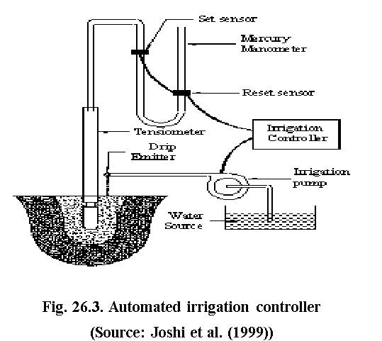
a) Tensiometer: The tensiometer is a device, which provides direct measure of tenacity with which water is held by the soil. Any change in soil water causes corresponding change in soil moisture tension. In automated irrigation controller, the tensiometer is modified to read change in soil moisture tension in terms of change in voltage or resistance, it consists of electro tensiometer, an electronic switching unit and a solenoid valve. Fig. 26.3 shows a typical automated irrigation controller using a tensiometer to trigger irrigation based on soil-water potential (Joshi et al. 1999).
b) Resistance Blocks: In this type of sensor, the electrical resistance between the electrodes varies with moisture content of resistance block. The moisture of resistance block is in equilibrium with the soil moisture. The presence of salt or salinity in irrigation water or soil affects the observations. The gypsum block and granular matrix type sensors are commonly used for soil moisture sensing and irrigation automation.
c) Gypsum Block: It consists of two electrodes inserted in a solid block of gypsum. Gypsum neutralizes the affect of salt content. Gypsum blocks are easy to use and economical. The limitation of this type of sensor is gypsum gets dissolved with water. Therefore, the calibration changes with the passage of time.
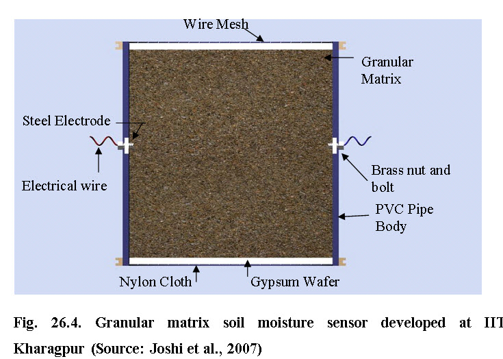
d) Granular Matrix: The granular matrix sensor uses granular matrix of standard size with uniform pore size. Two electrodes are inserted in granular matrix fill material, above which gypsum wafer supported with metallic or plastic screen. The gypsum wafer slowly neutralizes the salinity of the soil solution hence electrical resistance between the electrodes is unaffected. Particle size of the granular fill material and its compression determines the pore size distribution in sensor and their response characteristics. Such sensors require little maintenance during the growing season and suited for sensing soil water potential and automatic control of irrigation systems. They have advantages of low unit cost and simple installation procedures similar to those used for tensiometer. A granular matrix type soil moisture sensor developed at IIT Kharagpur is shown through Figure 26.4. These electrodes are connected to controllers. As the soil moisture replaces the air present in the voids of granular material thus results in reduction of electrical resistance between the electrodes and vice versa. The developed sensor is calibrated in terms of impedance versus soil moisture content. The sensor gives feedback to the central processing unit of the personal computer to automate micro-irrigation system (Joshi et al., 2007).
e) TDR based soil moisture sensor: Time Domain Reflectometry (TDR) is a reliable soil moisture measurement compared to other methods stated above because of their frequent calibration. This device has been recommended for automation of irrigation. This device determines dielectric constant of the soil by measuring the transit time of an electro-magnetic pulse created along the pair of parallel metallic rods of known length inserted in the soil. The empirical relationship between dielectric constant (K) and volumetric moisture content given by Topp et al. (1980) is
Qv = 0.053 + 0.0292K – 5.5 X 10⁻⁴ K2 + 4.3 X 10⁻⁶ K3 ……… (26.1)
Where
K = Dielectric constant (Ct l-2)
C = Velocity of light in free space (3 X 10⁸)
t = Travel time of voltage pulse measured by TDR
l = Length of probe, m
Such sensors have been evaluated in light soils both in laboratory and field conditions and it resulted in closer matching with the observed volumetric content.
f) Infrared sensors for leaf air temperature: Plant canopy temperature measured from a distance with an infrared thermometer can be used to detect plant water stress and signal irrigation needs before the crop exhibits any visual symptoms of drought. This is because water-stressed plants have a tough time in obtaining enough water from the soil to meet atmospheric demand, and this reduces evaporative cooling of their leaves. The Crop Water Stress Index (CWSI) method uses plant and air temperature and vapor pressure deficit of the air to determine whether a crop has adequate water (CWSI=0) or under severe water stress (CWSI= 1).
Infrared thermometers can be hand held or mounted on booms for continuous operation. Thermal scanners on board satellites or aeroplanes, map crop temperatures across an entire field or farm. Thermal data are used for irrigation scheduling (Gontia and Tiwari, 2008).
g) High frequency capacitance type soil moisture sensor: The capacitance of electrodes inserted in to soil operating at oscillation frequency (80-150 MHz) is dependent on the dielectric properties of the soil. The probes consists of two stainless steel rods of 100 mm long 6 mm diameter placed at 20 mm apart inserted in to the soil. The relative permittivity of such sensors is related to soil moisture content. Closer agreement between the observed soil water content and estimated volumetric content by gravimetric method for all types of soil has been reported for this type of sensor. However, difference in bulk density affects the performance of sensors.
26.2.7.2 Sensors for Climatological Parameters: Sensors for measuring various climatological parameters such as solar radiation, maximum and minimum temperature, wind speed, relative humidity, pan evaporation etc. are interfaced with the microprocessor computer to estimate evapotranspiration of crop and irrigation is commissioned based on evapotranspiration demand.
Reference:
Dhingra, D. and Kumar, Ashwani (2001). Automation of Micro-irrigation. Proc. International Conference on Micro and Sprinkler Irrigation System. 8-10. Feb 2000, Jain Irrigation Hills, Jalgaon, MS (India): 230-235.
Gontia, N. K. and Tiwari, K. N. (2008). Development of Crop Water Index for Scheduling Irrigation using Infrared Thermometry. Agricultural Water Management. 95:1144-1152.
Joshi, A. B. (2001). Automation in Micro-irrigation System, Proc. of International Conference on Micro and Sprinkler Irrigation System. 8-10. Feb 2000, Jain Irrigation Hills, Jalgaon, MS (India): 178-186.
Joshi Ajay, Tiwari K. N, Banerjee S. (1999). Automated Irrigation Controller Patent Application. # 6/Cal/99 dated 04-1-1999, IIT Kharagpur.
Joshi, et al. (2002). Automated Irrigation System. (Indian Patent No. 198539 dated 15.05.2012)
Joshi, et al. (2007). Granular Soil Moisture Sensor. (Indian Patent No. 212152 dated 21.12.2007)
Top, G. C., Davis, J. L. And Annan, A. P. (1982). Electromagnetic Determination of Soil Water Content using TDR. I . Application to wetting fronts and steep gradients. Soil Sci. Am. J. 46: 672-78.
Wang Dong, Susan A. O’Shaughnessy and Bradly King (2013). Automated Irrigation Management with Soil and Canopy Mapping (In Agricultural Automation Fundamentals & Practices. Edited by Zhang Qin and Pierce, F. J.) CRC Press Taylor & Francis, Chapman & Hall Book NW: 295-322.
Suggested Reading
Phene, C.J., C.P. Allee and J. Pierro. 1988. Measurement of Soil Matric Potential and Real Time Irrigation Scheduling. International Proceedings of Conference on Sensors & Techniques for Irrigation Management, Center for Irrigation Technology. Publication. 880502. Fresno, Calif.: California State University, 63-75.
Testezlaf, R., F.S., Zazueta and T.H. Yeager. 1997. A Real-time Irrigation Control System for Greenhouses. Applied Engineering in Agriculture, 13(3): 329.
Partranabis, D. 2011. Sensors and Transducers. PHI Learning Private Limited (Second Edition), New Delhi
Last modified: Thursday, 6 February 2014, 5:26 AM