Site pages
Current course
Participants
General
Module 1. Introduction about design and developmen...
Module 2. Study of special design features of trac...
Module 3. Study of basic design parameters for tra...
Module 4. Selection of different mechanical power ...
Module 5. Study of tractor steering and suspension...
Module 6. Design and analysis of tractor hitch sys...
Module 7. Design of a tractor hydraulic system
Module 8. Study of electrical, electronics and gui...
Module 9. Ergonomics, controls and safety features...
Module 10. Tractor testing
Module 11. General revision
Appendices & References
Lesson 10. Tractor clutches and brakes
1. Introduction
Power transmission system is the gear and/or hydraulic system having different components that transmits mechanical power from a prime mover (which can be an engine or electric motor), to some form of useful output device.
The power transmission system consists of:
(a) Clutches and Brakes
(b) Transmission gears
(c) Differential
(d) Final drive
(e) Rear axle
(f) Rear wheels
I. Clutches:
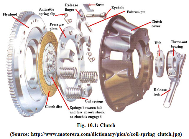
Clutch is a device, used to engage and disengage the tractor engine from the transmission gears and drive wheels. Clutch transmits power by means of friction between driving members and driven members (Fig. 10.1).
Functions of a clutch:
The internal combustion engine as used in a tractor must be cranked manually or by a special starting mechanism. For cranking, the engine is disconnected from the rest of the transmission unit by a suitable clutch. After starting the engine, the clutch is engaged to transmit power from the engine to the gearbox. This type of engine must attain a certain speed before it will have any power.
Changing the transmission gears must be permitted for the purpose of securing different traveling speeds. The gearbox must be kept free from the engine power, otherwise the gear teeth will be damaged and engagement of gear will not be perfect. This is done by clutch.
Stopping the belt pulley must be permitted without having to stop the engine. This is done by placing a clutch between the engine and the transmission gears and belt pulley.
II. Requirements of clutch:
-
It should have good ability of taking load without dragging, grabbing and slipping.
-
It should have higher capacity to transmit maximum power without slipping.
-
It should be convenient, accessible and easy to operate, adjust and repair.
-
Friction surface should be highly resistant to heat effect. The control by hand lever or pedal lever should be easy.
III. Types of clutch
Clutches are mainly of three types:
i. Friction clutch
ii. Dog clutch
iii. Fluid coupling
i. Friction clutch
A clutch in which one part turns the other by the friction between them. Friction clutch produces gripping action, by utilizing the frictional force between two surfaces. These surfaces are pressed together to transmit power.

(http://www.brickengineer.com/pages/anims/mechanisms/clutch-animation.gif)
While starting the engine, the clutch pedal is depressed. After the start of the engine, the clutch pedal is slowly released to increase the pressure gradually on frictional surface until there is no slip. Thus the driven plate is gripped firmly to the driving plate. Transmission of power depends upon the kind of material used for the friction members and intensity of the force, pressing them together.
Friction clutch is most popular in four wheel tractors (Fig. 10.2). Fluid clutch is also used in some tractors these days. Dog clutch is mostly used in power tiller.
Friction clutch may be subdivided into three classes:
i. Disc/Plate clutch
a. Single plate clutch or single disc clutch
b. Multiple plate clutch or multiple disc clutch
ii. Cone clutch
Frictional clutches are most commonly used because of following advantages:
Advantages of Friction Clutches:
Slips during engagement help the drive to pick up and accelerate the load with minimum shock.
They need not to be unloaded before engagement.
These can be used at high engagement speeds.
Slip under momentary shock loads, provides cushioning.
a) Single plate clutch:
This may be called single disc clutch.
It consists of:
Pressure plate
Clutch plate
Springs
Release fingers
The single disc clutch is a plate type of clutch in which a single thick iron plate is coated with friction material on both sides (Fig. 10.3). There is only one clutch plate in this type. The clutch plate is pressed against the flywheel of the engine by the spring loaded pressure plate. The pressure produced by a number of springs, located between the pressure plate and the housing, which is bolted to the flywheel, holds the friction surfaces firmly in contact. When the pedal of the clutch is depressed, the pressure plate is pushed back by the release fingers.
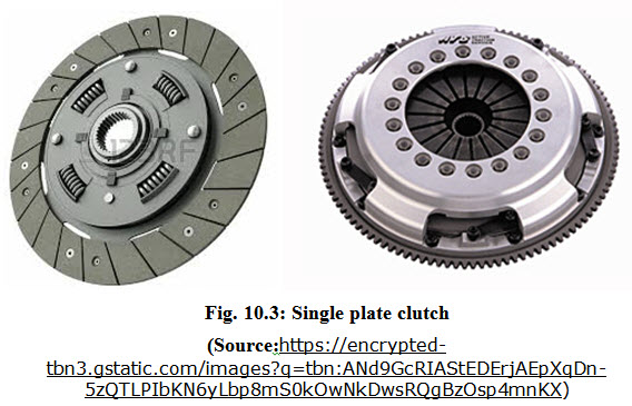
This releases the pressure from the clutch plate and disengages the clutch. Then the clutch plate stops rotating but the fly wheel continues to rotate. When the clutch pedal is released, the pressure plate forces them to turn together as one unit. Thus the power of the engine goes to the gear box for onward transmission to rear wheels. This type of tractor clutch plate is usually foot operated.
b) Multiple plate clutch:
This may be called multiple disc clutch. It can be twin-disk or three-plate type of clutch (Fig. 10.4). It differs from single-plate clutch in that the flywheel rims does not serve as a friction surface. It may also got a number of thin metal plates, arranged alternately to work as driving and driven members. One set is attached to the fly wheel and the other set is attached to the clutch shaft. If the plates are pressed together, the clutch is said to be engaged and the power is transmitted from the engine to the gear box for onward transmission to the rear wheels. This pressure is obtained by a set of heavy springs, fitted together in a housing.
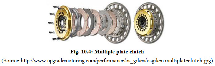
Engagement and disengagement of this type of clutch is very smooth due to larger surface area of friction members.
IV. Design of Disc Type Clutch:
There is a relationship between following parameters in a disc clutch:
Dimensions of disc.
Pressure applied to the friction surface.
Coefficient of friction and
Torsional moment developed.
Mathematically,
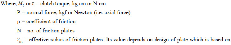
![]()
(i) Uniform pressure
(ii) Uniform axial wear
(i) Uniform pressure: When the friction surface is new and unworn and rigidly mounted, it is assumed that the normal force P is uniformly distributed over the entire area of clutch. And rm is taken as :

Where,
ro = outside radius of friction plate.
ri = inside radius of friction plate.
(ii) Uniform axial wear: The clutch is subjected to wear due to sliding friction and after the running in wear is ended, the wear will be uniform. The mean radius rm of the clutch is given by
![]()
When equal importance is given to durability and torsional moment, then
![]()
When high torsional moment capacity is needed and wear is not a serious problem, then
![]()
Where wear is a problem, then
![]()
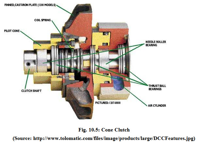
V. Cone Clutch:
The principal member of the cone-clutch assembly is a metal disk with a conical peripheral surface that engages with a similarly shaped recess in the flywheel (Fig. 10.5). The cone is faced with ordinary brake lining. A heavy spring placed behind the cone, exerts sufficient pressure to insure its positive engagement. A sleeve fastened to the cone extends back and is bolted to the transmission shaft. Therefore, the engagement if the clutch connects the gears with the engine. Disengagement is produced by sliding the cone and sleeve backward on the flywheel shaft extension against the spring pressure.
i. Advantages for cone clutch:
Force is concentrated at a large diameter.
Sufficient friction surface width is provided for durability.
A full 360º of lining material is available.
It is comparatively powerful for a given outside diameter and axial energizing force
ii. Design of Cone Clutch
The torsional moment developed by cone clutch is a function of
Inner radii of functional surface
Outer radii of frictional surface
The cone angle, θ
The force of engagement
Coefficient of friction of the contact surface
And,
![]()
Therefore,
![]()
And, axial force Fa is given by
![]()
It has been found that the term µcosθ is only 25% effective.
Therefore,
![]()
As θ→0 Mt →to infinity
At θ = 0 the cone becomes a drum and
At θ = 90º the cone becomes a single face disk clutch
Generally the value of θ varies from 7.5 to 30º depending on clutch facing material and type of disengagement required.
iii. Heat generated in clutch (Q)
The heat generated (Q) in a clutch is given by
![]()
Where, Q = heat generated in the clutch due to slippage, J
T = Average slip torque, N.m
Ns = Average slip RPM
t = Total slip time for the clutch, s
iv. Temperature of heat absorbing element of clutch (T)
The temperature of heat absorbing element of clutch (T) is given by
![]()
Where, T = average bulk temperature of clutch, ºC
Q = heat generated in clutch, J
M = total mass of heat absorbing element of clutch
Cp = specific heat of heat absorbing element, J/kg-ºC
To = Bulk temperature before engagement of clutch, ºC
v. Rate of energy generation in clutch (E)
The rate of energy generation in clutch is given by
![]()
Where, E = rate of energy generation in clutch, w/mm2
Ns = Average slip of clutch, RPM
T = Average slip torque in the clutch, N-m
a = Total facing area of clutch, mm2
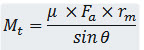
VI. Dog clutch:
It is a simple clutch having square jaws, which are used to drive a shaft in either direction. It is mostly used in power tillers (Fig. 10.6). A dog clutch is a type of clutch that couples two rotating shafts or other rotating components not by friction but by interference. The two parts of the clutch are designed such that one will push the other, causing both to rotate at the same speed and will never slip. Dog clutches are used where slip is undesirable and/or the clutch is not used to control torque. Without slippage, dog clutches are not affected by wear in the same way that friction clutches are. Dog clutches are used inside manual automotive transmissions to lock different gears to the rotating input and output shafts. A synchromesh arrangement ensures smooth engagement by matching the shaft speeds before the dog clutch is allowed to engage.
A good example of a simple dog clutch can be found in a Sturmey-Archer bicycle hub gear, where a sliding cross-shaped clutch is used to lock the driver assembly to different parts of the planetary geartrain.
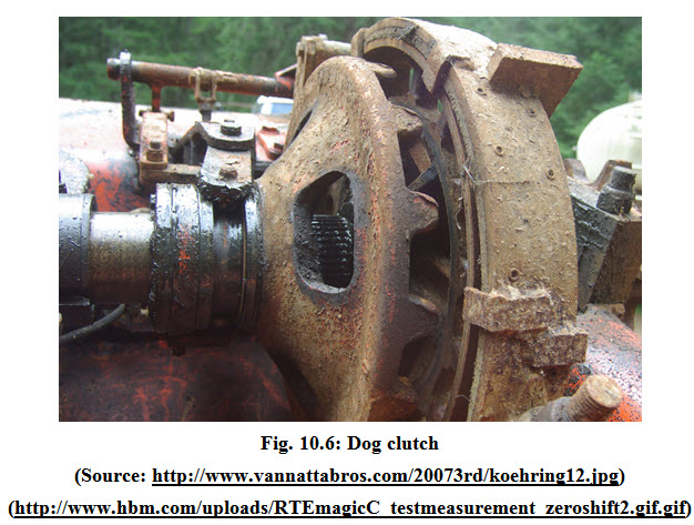
VII. Fluid coupling:
Fluid coupling consists of a driving member and a driven member - an impeller with radical vanes, housed in a suitable casing (Fig. 10.7). A coupler is mounted on the engine crankshaft and is 3/4th filled with suitable oil. A spring loaded sealing ring is provided to make the driven shaft oil tight. At the rotation of the crankshaft, the oil is thrown out by centrifugal force from the center to the outer edge of the impeller, increasing the velocity and the energy of the oil. It then enters the runner at the outer portion and flows towards the center, causing rotation to the runner unit. As long as impeller and runner rotate at different speeds, the oil continues to circulate uniformly but when the impeller and runner start running at same speed, the circulation of oil stops. The coupling does not increase the applied torque but only transmits the torque in an uniform manner.
The main features of fluid coupling are:
Absorption of shock and vibration
Smooth starting and
Easy operation
VIII. Brakes:
Brakes are classified as either external, internal or bond brakes. External shoe brakes are further classified into single and double block shoe brakes. External shoe brakes consist of shoes or blocks which are pressed against the rotating surface of the brake drum. Fig. 10.2 shows a schematic representation of an external single shoe brake. The design of internal shoe brakes largely depends on force, torque, coefficient of friction and the radius of the rotating drum. Fig. 10.3 shows a schematic representation of an internal shoe brake.
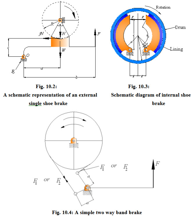
Band brakes are flexible bands wrapped partly around the drum. Pulling the band tightly against the drum actuates them. The design of band brakes is dependent on force, angle of wrap, coefficient of friction, pressure on the shoes and radius of the drum. A diagram of a simple two way band brake is shown in fig. 10.4.
i. Heat Generated
When the brake is actuated, energy is absorbed, which in turn is dissipated as heat energy. This design is dependent on pressure, area of contact, peripheral velocity, coefficient of friction, potential energy, and kinetic energy, coefficient of heat transfer and area of the radiating surface.
Last modified: Monday, 7 April 2014, 4:17 AM