Site pages
Current course
Participants
General
Module 1. Introduction about design and developmen...
Module 2. Study of special design features of trac...
Module 3. Study of basic design parameters for tra...
Module 4. Selection of different mechanical power ...
Module 5. Study of tractor steering and suspension...
Module 6. Design and analysis of tractor hitch sys...
Module 7. Design of a tractor hydraulic system
Module 8. Study of electrical, electronics and gui...
Module 9. Ergonomics, controls and safety features...
Module 10. Tractor testing
Module 11. General revision
Appendices & References
Lesson 12. Introduction and selection of different components for steering systems.
1. Introduction
The most conventional steering arrangement is to turn the front wheels using a hand–operated steering wheel which is positioned in front of the driver having steering column, which may contain universal joints, to allow it to deviate somewhat from a straight line. Other arrangements are sometimes found on different types of vehicles, for example, rear–wheel steering in combine harvesters. Tracked vehicles such as bulldozers and tanks usually employ differential steering that is, the tracks are made to move at different speeds or even in opposite directions, using clutches and brakes, to bring about a change of course or direction..
The steering system works with the suspension system to provide directional control with a comfortable amount of steering effort. It must do this while allowing for the necessary movement in the vehicle’s suspension system. Some parts serve both systems. The steering system consists of a steering gear, steering linkage, a steering column and a steering wheel. Two types of steering systems are widely used in tractor i.e. conventional steering and rack-and-pinion steering.
I. Basic geometry:
The basic aim of steering is to ensure that the wheels are pointing in the desired directions. This is typically achieved by a series of linkages, rods, pivots and gears. One of the fundamental concepts is that of caster angle - each wheel is steered with a pivot point ahead of the wheel; this makes the steering tend to be self-centring towards the direction of travel.
The steering linkages connecting the steering box and the wheels usually conforms to a variation of Ackermann steering geometry (Fig. 12.1), to account for the fact that in a turn, the inner wheel is actually travelling a path of smaller radius than the outer wheel, so that the degree of toe suitable for driving in a straight path is not suitable for turns. The angle the wheels make with the vertical plane also influences steering dynamics (see camber angle) as do the tires.
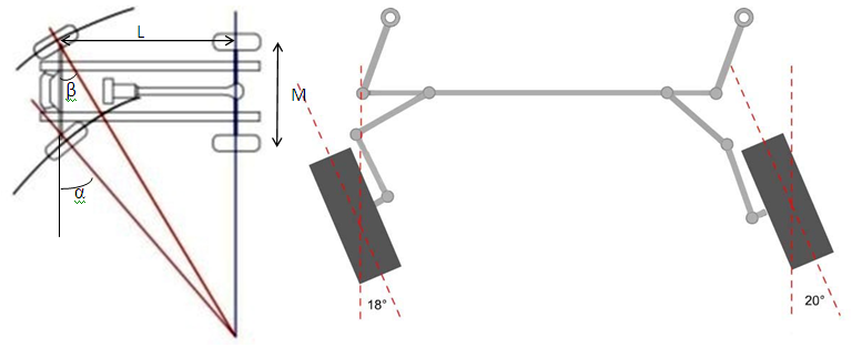
Fig. 12.1: Ackermann steering geometry and caster angle (Courtesy Melior Inc. 2004)
The steering geometry where the turning wheels advance without any lateral slip is the ideal Ackermann geometry. According to this geometry (Fig. 12.1) the steered wheels should always be rolling around a common center located on the extension of the rear axle. In other words, the inside and the outside steering angles should satisfy the following relationship:
![]() ... (12.1)
... (12.1)
Where
ß is the angle between axis of outer wheel with tie rod
α is the angle between axis of inner wheel with tie rod
M is the distance between the two points of kingpin extension on the ground
L is the wheelbase of vehicle
If the steering systems not optimally designed, cannot comply with ideal Ackermann geometry, as a result of this inaccuracy in steering geometry, certain amount of lateral slip of wheels occurs during turns. This lateral slip increases the rolling resistance, tire wear and steering effort.
Caster angle indicates kingpin pivot line and gray area indicates vehicle's tire with the wheel moving from right to left. A positive caster angle aids in directional stability, as the wheel tends to trail, but a large angle makes steering more difficult.
Types of Steering Systems
1. Conventional Steering:
The worm and sector was an older design used for Willys and Chrysler vehicles, and the Ford Falcon. Older designs often use the re-circulating ball mechanism, which is still found on many vehicles (Fig. 12.2). This is a variation on the older worm and sector design; the steering column turns a large screw (worm gear) which meshes with a sector of a gear, causing it to rotate about its axis as the worm gear is turned; an arm attached to the axis of the sector moves the Pitman arm, which is connected to the steering linkage and thus steers the wheels. The re-circulating ball version of this type reduces the considerable friction by placing large ball bearings between the teeth of the worm and those of the screw; at either end of the apparatus the balls exit from the two pieces into a channel internal to the box which connects them with the other end of the apparatus, thus they are "re-circulated".
It is also referred to as Re-circulating Ball or Worm Gear steering (Fig. 12.3) for the type of gear it uses or on the basis of the shape formed by the linkage set like parallelogram or trapezium or simple linkage of steering.
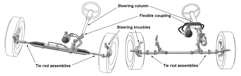
Fig. 12.2: Conventional steering System (Courtesy Melior Inc. 2004)
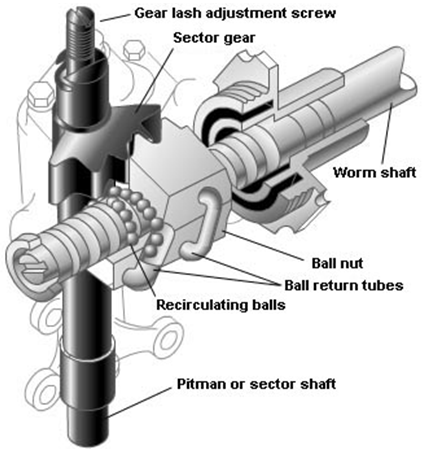
Fig. 12.3: Recirculating ball mechanism for steering (Courtesy Melior Inc. 2004)
2. Rack-and-pinion Steering:
Rack-and-pinion steering transmits circular motion from the steering wheel to a pinion that meshes with teeth on a flat rack (Fig. 12.4). The pinion moves the rack in a linear direction for steering the wheels. It is simpler and less expensive to produce than conventional steering systems. The rack and pinion design has the advantages of a large degree of feedback and direct steering "feel". A disadvantage is that it is not adjustable, so that when it does wear and develop lash, the only alternate is replacement.
The recirculating ball mechanism has the advantage of a much greater mechanical advantage, so that it was found on larger, heavier vehicles while the rack and pinion was originally limited to smaller and lighter ones; due to the almost universal adoption of power steering, however, this is no longer an important advantage, leading to the increasing use of rack and pinion on newer vehicles. The recirculating ball design also has a perceptible lash, or "dead spot" on center, where a minute turn of the steering wheel in either direction does not move the steering apparatus; this is easily adjustable via a screw on the end of the steering box to account for wear, but it cannot be entirely eliminated because it will create excessive internal forces at other positions and the mechanism will wear very rapidly. This design is still in use in trucks and other large vehicles, where rapidity of steering and direct feel are less important than robustness, maintainability, and mechanical advantage.
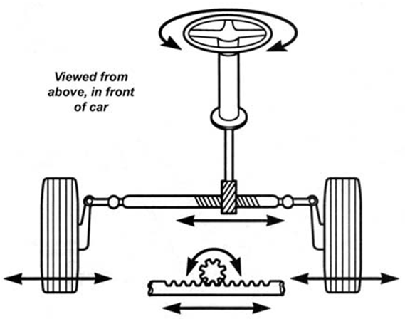
Fig. 12.4: Rack and pinion type steering system (Courtesy Melior Inc. 2004)
3. Power assisted steering:
Power assisted steering helps the driver of a vehicle to steer by directing some of its power to assist in swivelling the steered road wheels about their steering axes. As vehicles become heavier along with increase in tyre width and diameter, the effort needed to turn the wheels about their steering axis increases. To alleviate this auto makers have developed power steering systems: or more correctly power-assisted steering also for off road vehicles like tractors.
There are two types of power steering systems;
(i) Hydraulic power steering (HPS)
(ii) Electric or electronic power steering (EPS).
(i) Hydraulic Power Steering (HPS): HPS can again be classified in two type of steering
(a) Power rack-and-pinion steering
(b) Integral power steering gearbox – Conventional recirculating ball steering gear with a hydraulic control system.
(a) Power rack-and-pinion steering systems:
In this system there is a power cylinder/hydraulic cylinder inside the rack or gear housing and a double-acting, hydraulic piston in the power cylinder that acts upon the rack (Fig. 12.5). Control valve mechanism located in the steering gear senses and controls power assist. Hydraulic lines or steel tubing from the control valve to the power cylinder that carries the power steering fluid. Most power rack-and-pinion units have a small tube that runs along the housing and connects to each bellows boot. This tube allows the air pressure in the bellows boots to equalize from one side to the other during turns. The power cylinder and piston are precisely machined and sealed with rubber O-rings. In operation, fluid is directed to a chamber of the power cylinder on either side of the rack. This fluid creates pressure to move the piston and thus the rack to the left or right. To sense and control assist, two types of control valves are used: either rotary control valves, or a spool control valve. Rotary control valves use a torsion bar attached to the input shaft to make the control valve move, aligning oil passages to the proper chamber. On spool valve units, the spool valve detects the thrust action of the input shaft caused by attempting to turn the steering wheel, and directs fluid to the proper chamber of the power cylinder.
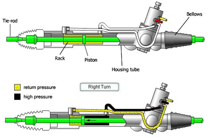
Fig. 12.5: Hydraulic power steering system (Courtesy Melior Inc. 2004)
(b) Integral power steering systems
This type of steering system is commonly used with linkage-type steering. Steering gearbox contains a conventional worm and-sector gear (Fig. 12.6). The hydraulic power piston and directional control valve are mounted inside the gearbox housing. As with power rack-and-pinion units, the valve may be a spool valve or a rotary valve with a torsion bar. When the steering wheel is in the straight-ahead position, the valve maintains equal pressure on both sides of the power piston. Oil flows back to the pump reservoir. During a turn, the control valve routes oil to one side of the power piston, which pushes it in the desired direction to provide assist. The oil on the non-pressurized side of the piston is forced back through the control valve and to the pump reservoir.
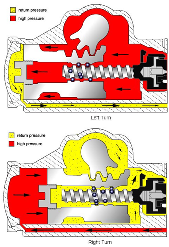
Fig. 12.6: Integral power steering system (Courtesy Melior Inc. 2004)
(ii) Electric Power Steering (EPS):
Computer-controlled electric power rack steering systems are used on some vehicles (Fig. 12.7). These systems use a small electric motor within the housing to assist in moving the rack. Some include a recirculating ball steering gear. Computer-controlled electric systems typically use inputs from the antilock brake wheel speed sensors, steering angle and steering effort sensors, and other inputs to provide the proper amount of steering assist.
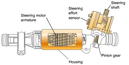
Fig. 12.7: Computer-controlled Electric Assist Rack-and-pinion type steering system (Courtesy Melior Inc. 2004)
Comparison between HPS and EPS:
A hydraulic power steering (HPS) uses hydraulic pressure supplied by an engine-driven pump to assist the motion of turning the steering wheel. Electric power steering (EPS) is more efficient than the hydraulic power steering, since the electric power steering motor only needs to provide assistance when the steering wheel is turned, whereas the hydraulic pump must run constantly. In EPS, the amount of assistance is easily tunable to the vehicle type, road speed, and even driver preference. An added benefit is the elimination of environmental hazard posed by leakage and disposal of hydraulic power steering fluid. In addition, electrical assistance is not lost when the engine fails or stalls, whereas hydraulic assistance stops working if the engine stops, making the steering doubly heavy as the driver must now turn not only the very heavy steering—without any help—but also the power-assistance system itself
4. Crab steering
Crab steering is a special type of active four-wheel steering (Fig.12.8). It operates by steering all wheels in the same direction and at the same angle. Crab steering is used when the vehicle needs to proceed in a straight line but under an angle or when the rear wheels may not follow the front wheel tracks i.e. to reduce soil compaction when using rolling farm equipment.
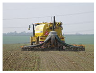
Fig 12.8: Agricultural slurry applicator using crab steering to minimise soil compaction
Last modified: Monday, 7 April 2014, 6:09 AM