Site pages
Current course
Participants
General
Module 1. Introduction about design and developmen...
Module 2. Study of special design features of trac...
Module 3. Study of basic design parameters for tra...
Module 4. Selection of different mechanical power ...
Module 5. Study of tractor steering and suspension...
Module 6. Design and analysis of tractor hitch sys...
Module 7. Design of a tractor hydraulic system
Module 8. Study of electrical, electronics and gui...
Module 9. Ergonomics, controls and safety features...
Module 10. Tractor testing
Module 11. General revision
Appendices & References
Lesson 15. Kinematic and force Analysis of hitch system geometry
1. Introduction
The hitch system geometry and types of motions needed for various components are decided based on functional requirements, necessary motions, depth control, dynamic load transfer, center-ability, trailing characteristics, lift capacity and stability. The hit and miss method is used to arrive at hitch system geometry both in horizontal plane and vertical plan.
2. Kinematic Analysis
This analysis is done to study motions of various components of the hitch system. Actual dimension of all components and their relative angles are actually measured to position them in space (to the scale). The kinematic analysis is then done in vertical-longitudinal, horizontal, and vertical lateral planes as discussed below:
(i) Vertical- Longitudinal Plane
All dual links are superimposed and hydraulic system is adequately modified to represent actual controls. The schematic of an actual hitch system with draft control (by sending it from the lower link) is shown in Fig. 15.1. In all, there are ten components, i.e. (1) tractor body, (2) upper link, (3) implement, (4) lower link, (5) loading sensing torque arm bellcrank, (6) lift link, (7) lift arm, (8) piston rod, (9) piston and (10) lever replacing hydraulic system. The total number of IC of the hitch are:
No. of links (N) =10
No. of IC =[N.(N-1)/2]/2 =45
No. of joints (G) =13
Degrees of Freedom =3(N-1) -2G =1
Thus, linkage is constrained with a definite rate relationship between all links since degree of freedom is one. This means if one link moves, all links move with it. The virtual hitch point will always be along the line of upper link (link 2). It is at the intersection of upper and lower links for free float state and at the intersection of line of PV and upper link for restrained state. The velocity and acceleration diagrams can be constructed to find inertial forces and torque acting on each link. The system can also be analyzed with regard to swap of each link as cylinder moves from minimum to maximum position.

Fig. 15.1: Schematic of hitch system in vertical longitudinal plane
(ii) Horizontal Plane
In horizontal plane, the hitch system is considered to be a four bar linkage, i.e. (1) tractor body, (2) upper link, (3) lower link and (4) implement. It gives a total of six IC. The degree of freedom is the same as for vertical – longitudinal plane. The direction of motion of any point in horizontal plane is perpendicular to the line joining the IC for the link on which the point lies. Similarly, velocity and acceleration diagram of the four bar linkage can be analyzed to find inertial forces and torque acting on the links.
(iii) Vertical Lateral Plane
Most implement that are not much wider than tractor are operated with rotational restraint in this plane. Thus, hitch is rigid with no degree of freedom in the vertical lateral plane. The implements which are wide relative to tractor are not used with restraint in this plane. The lift link restraint is made free to telescope. The schematic in the above case is shown in Fig. 15.2. The instantaneous center or virtual hitch point F is above surface. The implement will rotate relative to the tractor about point F. Since the IC is above ground, the implement bottoms will have to shift laterally in the soil during rotation. The amount of lateral movement U of the implement bottom depends on the distance W, the bottom is below F for a given rotational angle. Thus, U can be made small if W is small. Hence, moving F lower is desirable but it should not be done without considering its effect in other planes.

Fig. 15.2: Schematic of hitch system in vertical lateral plane
3. Force Analysis
The forces on the hitch system are a system of non-coplanar, non-concurrent and non-parallel forces. To have equilibrium, the following conditions must be considered:
∑ FV = 0 ∑ MV = 0
∑ FL = 0 ∑ ML = 0
∑ FH = 0 ∑ MH = 0
This means the forces in the vertical, lateral and horizontal directions must be in balance and moments in vertical-lateral (V-H), vertical-longitudinal (L-V) and horizontal (L-H) planes must be in balance. Equations can be developed for complete force analysis in three planes for better results. However, graphical technique can also be applied to find forces at various points so as to draw free body diagram of each link. Then, each link is analyzed with regard to type of loading, i.e., tension/compression, torsion, bending and shear. The cross-section of each component is then determined by using machine design principles. Table 15.1 gives type of load acting on each link.
4. Transport Shock forces
Rear mounted implements impose a cantilever type of load through the hitch system. The combination is rigid to such a degree that implements transported over rough terrain will be exposed to high shock loads due to some looseness in the linkage. The sensing system is generally not cushioned for protection. The shock loads can be reduced by having a pressure relief value in the hydraulic cylinder. The shock factors with a proper relief valve can be still as high as six for upper link and five for lift link for 60 kW tractor for a heavy and long implement. However, in case of close coupled tool mounted on a 60 kW tractor, the shock factor can be as high as eight in upper link and four in lift link.
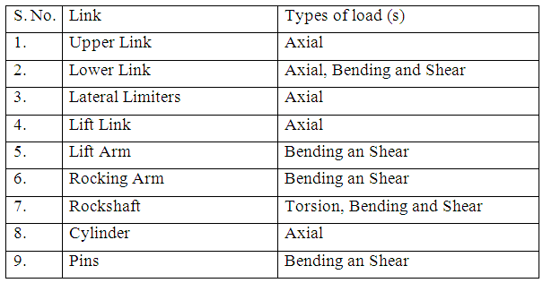
Table 15.1: Types of loads on various links of the hitch system
Last modified: Monday, 7 April 2014, 7:10 AM