Site pages
Current course
Participants
General
Module 1. Introduction about design and developmen...
Module 2. Study of special design features of trac...
Module 3. Study of basic design parameters for tra...
Module 4. Selection of different mechanical power ...
Module 5. Study of tractor steering and suspension...
Module 6. Design and analysis of tractor hitch sys...
Module 7. Design of a tractor hydraulic system
Module 8. Study of electrical, electronics and gui...
Module 9. Ergonomics, controls and safety features...
Module 10. Tractor testing
Module 11. General revision
Appendices & References
Lesson 19. Electrical System of tractor
1. Introduction
Electrical and electronic systems have evolved over the years to become an essential element of modern off-road vehicles. A modern off-road vehicle typically incorporates an electrical system having its own power generation, storage, and distribution. Vehicle controls and diagnostics may have dozens of electronic computer-based controllers integrated into its system. Electrical system of all the tractors is almost same except one or two alterations. In some of the makes of the tractors, alternator has been introduced instead of dynamo for the recharging of a battery.
Functions of electrical system for a conventional off-road vehicle are:
Engine starting
Lighting (work and safety)
Sensing, display, and control
Air conditioning/Ventilation
Accessory may include windscreen wiping, entertainment systems, radio, etc
2. Components of an electrical system
An electrical system of a tractor consists of the following parts/system, which are explained below
Battery
Charging System
Regulating systems
Starting system
Relays and fuses
i. Battery:
Since the source of electricity in a tractor is the battery, let's see how it works: A battery is an electrochemical device which converts chemical energy into electrical energy. Tractors use "lead-acid" batteries. A lead-acid battery uses a series of lead dioxide plates for its positive (+) terminal and porous, soft lead for its negative plates. All the plates are arranged alternately and submerged in a solution of sulfuric acid and water. The cross section of a battery is shown in Fig. 19.1. The positive plate's lead oxide is a compound of lead and oxygen. Sulfuric acid is a compound of hydrogen and the sulfate radical (SO4), so the acid's chemical designation is H2SO4.

Fig. 19.1: Cross section of a battery
Chemically, when a battery is connected to an external load (a device which uses electricity) it begins to discharge. As that happens, the lead in the positive plate combines with the sulfate of the acid, forming lead sulfate (PBSO4) in the positive plate. Oxygen in the positive plate combines with hydrogen from the acid to form water (H2O), which reduces the concentration of the acid in the electrolyte. Also, the pure lead in the negative plate combines with the sulfate, forming lead sulfate and making the positive and negative plates more alike in chemical composition. Electrons are released during this reaction, creating electrical current at a specific voltage (2 volts per cell, with 6 cells in a 12-volt battery, described below). One model HMT 7511 was installed with two batteries each of 12 V connected in parallel to meet more cranking power required to start the high hp engine.
Chemical reactions:
The chemicals used in a Battery are as follows
1. Sponge Lead (Solid) in Cathode (-ve) plates
2. Lead Oxide (Paste) in Anode (+ve) plates
3. Sulphuric Acid (Liquid)
The chemical reactions take place between the three chemicals in the battery. In the presence of sulphuric acid, the electrons from one group of plates collect on the other group of plates.
The following chemical reactions take place while charging and discharging (Fig. 19.2)
While charging
At Anode (+ve Plate):![]()
At Cathode (-ve Plate): ![]()
During Discharge: The acid H2SO4 attacks lead to form PBSO4 (Lead sulphate)
At Anode: ![]()
At Cathode combines with it to form ![]()
So both at anode (+ ve) and at Cathode (-ve) is formed. During this process water is also formed which dilutes sulphuric acid and thereby decreases its specific gravity. This the battery converts electrical energy into chemical energy during charging and chemical energy into electrical energy during discharging.
The capacity of a fully charged battery falls down to a much lower value in fully discharged state. To know the capacity of battery two methods are adopted.
1. Ampere Hour efficiency
2. Watt Hour efficiency
Efficient (AE) = Ah at full discharge/Ah at full charge
Efficiency(Wh) = Wh out put at full discharge/Wh input at full charge

Fig. 19.2: Charging and discharging of a battery
Battery Testing:
A battery can be tested to ascertain its condition by the following tests.
Specific gravity test
Open Volt test
High discharge test
Cadmium tip test
Specific gravity test: While the chemical reaction taking place in the battery during discharge, the electrolyte becomes dilute to form water. The proportion of water goes on increasing as the discharging continues. The relative amounts of water and acid is determined by the specific gravity test. This is done by Hydrometer.
The Meter of Hydrometer ranges as follows:
1.260 to 1.280 : Fully charged
1.230 to 1.250 : ¾ charge
1.200 to 1.220 : ½ charge
1.170 to 1.190 : Very little charge
1.110 to 1.130 : completely discharged
Open Volt test: The Open circuit voltage of a fully charged battery cell is about 2.1 volts. This can be measured with the help of a voltmeter. It can be observed that a charge of 0.01 Volt of open circuit voltage is equivalent to a charge of 0.010 in the specific gravity of the electrolyte.
High discharge test: High Voltage of current is required for cranking the starting motor. To satisfy this condition, high discharge test is done with the help of cell voltage tester.
Cadmium Test: The test is done to ascertain whether the battery plates are defective or not. It is done with help of cadmium rod enclosed in a perforated ebonite tube. The rod is immersed in the electrolyte and connected to the negative terminal of a Voltmeter. Its positive terminal is connected alternately to the positive and negative terminals of a battery cell. When connected with positive terminals, the voltage reading should not be less than 2.5 Volts. If it is less it indicates defective positive plates. When connected with negative plates, if it is more than 2.5 Volts, it indicates defective negative plates.
ii. Charging System (Generators or Alternators):
How the battery gets charged. In older vehicles this was done with a generator. After that time all switched to alternators.
Generator:
The basic principle at work here is that electricity produces magnetism. Conversely, magnetism produces electricity. If a current-carrying coil of wire is placed around a bar of steel, the bar will become magnetized. The more turns of wire and the stronger the current, the more powerful the magnet. By placing a soft iron core within the coil, the magnetic force lines are concentrated and strengthened. As there is less electrical resistance in the iron than in the surrounding air, the force lines will follow the core.
The various parts of a generator are shown in Fig. 19.3. The two pole shoes of a generator are constructed in this way. Rather than use magnets - which are heavy and expensive - many turns of wire are wound around the pole shoes. When a current passes through these windings the pole shoes become electromagnets, called FIELD COILS. These two field coils are connected in series (current passes through one and then through the other) and wound so that one becomes the North Pole and the other the south pole of the magnetic field.

Fig. 19.3: Different parts of a generator
Inside the generator is a spinning central shaft which is supported in bearings at each end. Loops of wire (armature windings) are wound on a special laminated holder called the ARMATURE. The armature is turned by placing a pulley on one end of the shaft and driving it with a V-belt from the engine's crankshaft, as seen in the figure. Attached to the armature are electrical contact segments, called the COMMUTATOR. These segments are electrically insulated from the armature - and each other - but each is soldered to one of the armature windings. It is the commutator which distributes electricity to the armature in an on-off manner, creating a magnetic field around the armature. Riding over the spinning commutator segments are carbon "brushes". These brushes are held in spring-loaded brackets and that pressure holds them against the commutator. It is the brushes which wear out over time and require replacement.
Generator Working:
When the generator armature first begins to spin, there is a weak residual magnetic field in the iron pole shoes. As the armature spins, it begins to build voltage. Some of this voltage is impressed on the field windings through the generator regulator called voltage regulator. This impressed voltage builds up a stronger winding current, increasing the strength of the magnetic field. The increased field produces more voltage in the armature. This, in turn, builds more current in the field windings, with a resultant higher armature voltage. This voltage could, of course, continue to increase indefinitely, but it is limited (by regulation) to a pre-set peak. At this point all this sounds like perpetual motion, doesn't it? Remember, though, that the energy driving all this is the engine's crankshaft!
Alternators
Generators produce Direct Current. Alternator produces an A.C. that in turn must be rectified or converted into D.C. and then stored in a battery. Alternators are more compact than dynamo (generators) systems and can supply more current at low speeds because at idle engine speeds they run at double the engine speed. Hence life of a battery is increased with the alternators.
Alternators have the advantage of producing far more current at low speeds than generators, thus allowing more and more accessories in the vehicle. In an alternator, the "field" windings are placed around the spinning central shaft rather than on "shoes" as in the generator (Fig. 19.4). Two iron pole pieces - cast with "fingers" - are slid on the shaft, covering the field winding so that the fingers are interspaced. The fingers on one pole piece form the North poles and the fingers on the other form the South poles. This assembly is called the ROTOR. Surrounding the rotor are a series of windings around laminated iron rings, attached to the alternator's case. This assembly is called the STATOR. The engine's crankshaft spins the rotor.

Fig. 19.4: Cut view of a typical alternators
Direct current from the battery is fed through into the rotor's field coil by using brushes rubbing against slip-rings. One end of the field coil is fastened to the insulated brush, while the other end is attached to the grounded brush. As the pole fields pass through the stator, current is electromagnetically produced (as in the generator) but since the rotor is composed of alternating North and South poles the current produced flows in opposite direction every 180-degrees of rotation. In other words, the current is "alternating". Difference in working of a generator and an alternator is shown in Fig. 19.5.
Why this is more efficient, as the stator windings are made up of three separate windings. This produces what is known as three-phase AC. When only one winding is used, single-phase current results (like in a generator). In effect, the alternator produces three times the current of a generator for the same effort on the engine's part. Also, alternators are considerably lighter and smaller than generators.
There's a small problem with alternators, though. AC electricity doesn't work in a tractor. The tractor's electrical system - and battery - need DC. Therefore, the alternator's output is "rectified" into DC. This is done by passing the AC into silicon diodes. Diodes have a peculiar ability to allow current to flow readily in one direction only, stopping the flow if the direction reverses. Multiple diodes are arranged in alternators so that current will flow from the alternator to the battery (in one direction only, creating DC) but not from the battery to the alternator.
In actual operation, the voltage regulator senses the battery voltage and overall demand on the tractor's electrical system. When charging is needed, the regulator applies battery voltage to the stator's brushes and this creates the electrical field for charging. As the system's demand for charging decreases the voltage to the brushes cuts off. All of this occurs many times per minute, with the system turning on and off repeatedly to keep everything at optimum operating efficiency.

Generator Alternator
(Stationary magnetic field) (Rotating magnetic field)
Fig. 19.5: Difference in working of generator and alternator
iii. Regulating system
As, there is no system of internally controlling the output of an alternator or in other words, the faster it spins the more voltage goes into the electrical system. If this weren't controlled the generator would damage the battery and burn out the lights. Also, if the generator weren't cut out from the tractor's circuitry when not running, the battery would discharge through its case.
That's where the REGULATOR (commonly called the Voltage Regulator, but that's only one component of the system) comes in. Regulators have seen many design improvements over the decades, but the most commonly used electro-mechanical regulator is the three-control units in one box type. These are explained below,
(a) Cutout Relay
Sometimes called the circuit breaker, this device is a magnetic "make-and-break" switch. It connects the generator to the battery (and therefore the rest of the tractor) circuit when the generator's voltage builds up to the desired value. It disconnects the generator when it slows down or stops.
The relay has an iron core that is magnetized to pull down a hinged armature. When the armature is pulled down a set of contact points closes and the circuit is completed. When the magnetic field is broken (like when the generator slows down or stops) a spring pulls the armature up, breaking the contact points.
An obvious failure mode is the contact points. As they open and close, a slight spark is generated, eventually eroding the material on the points until they either "weld" themselves together or become so high in resistance that they won't conduct current when closed. In the first case the battery would discharge through the generator overnight and in the second there would be no charging to the system.
(b) Voltage Regulator
Another iron core-operated set of contact points is utilized to regulate maximum and minimum voltage at all times. This circuit also has a shunt circuit (a shunt re-directs electrical flow) going to ground through a resistor and placed just ahead (electrically) of the points (Fig. 19.6). When the points are closed the field circuit takes the "easy" route to ground but when the points are open the field circuit must pass through the resistor to get to ground.
The field coil on the generator is connected to one of the voltage regulator contact points. The other point leads directly to ground. When the generator is operating (battery low or a number of devices running) its voltage may stay below that for which the control is set. Since the flow of current will be too weak to pull the armature down the generator field will go to ground through the points. However, if the system is fully charged the generator voltage will increase until it reaches the maximum limit and current flow through the shunt coil will be high enough to pull the armature down and separate the points.
This cycle is repeated over and over in real time. The points open and close about 50 to 200 times per second, maintaining a constant voltage in the system.

Fig. 19.6: View of a typical voltage regulator
(c) Current Regulator
Even though the generator's voltage is controlled it is possible for its current to run too high. This would overheat the generator, so a current regulator is incorporated to prevent premature failure (Fig. 19.7).
Similar in appearance to the voltage regulator's iron core, the current regulator's core is wound with a few turns of heavy wire and connected in series with the generator's armature. In operation, current flow increases to the predetermined setting of the unit. At this time, current flow through the heavy wire windings will cause the core to draw the armature down, opening the current regulator points. In order to complete the circuit the field circuit must pass through a resistor. This lowers current output, points close, output increases, points open, output down, points close, and so on. The points, therefore, vibrate open and closed much as the voltage regulator's points do, many times every second.
Because they are mechanical, voltage regulators are easy to troubleshoot. If you study the function of each of the three parts and how they interrelate, it becomes obvious which part is malfunctioning, depending upon symptoms. The point gaps and spring pressures determine the voltage/current limits and they are exceedingly hard to adjust. Sometimes it can be done on the tractor using a voltmeter, but generally it is best to replace the entire regulator assembly when a certain part of it fails. Factory assembly of regulators required relatively sophisticated measurement instruments. Adjusting them by "feel" is a matter of luck, and frequently can result in damage.
It wasn't long thereafter that the automobile companies converted to transistor voltage regulators. Utilizing Zener diodes, transistors, resistors, a capacitor and a thermistor, these regulators maintain proper voltage and current flow throughout the system. Their circuitry operates as fast as 2,000 times per second and they are tremendously reliable. On the other hand, these regulators aren't easy to repair. They are designed to be thrown away and replaced. Alternators provide three times the current and weigh much less than their old counterparts.

Fig. 19.7: Voltage and current regulators
d. Starting System:
Electrical system only needs 80 to 100 amps of current for general running, even when all accessories are operating. Then, why battery does have a rating of 450 to 740 amps or even more. The main reason for the battery's storage capacity is to operate the starter, and a quick look at the numbers will demonstrate why this is so important:
Let's take a 500-amp-rated battery for example. At 12 volts, this 500 amp battery is capable of putting out 6000 watts. We need all the wattage we can get to develop enough horsepower to turn the engine over for ignition and one horsepower (or the power necessary to lift 550 pounds (249.47 kg) one foot in one second) equals 746 watts. Our battery, therefore, puts out just over eight horsepower. That's just enough for a couple hundred revolutions of the engine before the charge is exhausted. Starters are incredibly strong motors that work in a hostile environment. They are the most important part of the starting system (Fig. 19.8) or circuit, consisting of the following:
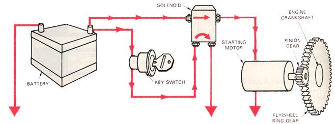
Fig. 19.7: Starting system of a tractor
Flywheel ring gear - This is a toothed ring that is fitted to the outside of the engine's flywheel. Matching teeth on the starter motor mesh with this gear in order to spin the crankshaft.
Starter solenoid (Relay) - The starter solenoid has very large contacts to carry the battery's full current. Its wire coil is actuated by a smaller current from the ignition switch, at which time the iron core slams down to make contact and turn on the starter motor. Most non-Ford starter motors employ a solenoid built into the motor itself. This type of solenoid not only provides the motor's electrical power but also mechanically engages the starter's drive gear onto the flywheel. It is commonly known as the BENDIX type of solenoid. Such solenoids operate in three stages, the disengaged, partially engaged and engaged. In the disengaged position the drive gear is released and no current is flowing. In the partially engaged stage, current from the starter switch flows through both the pull-in and the hold-in coils. Both coils draw the plunger inward, causing it to pull the shift lever and engage the pinion gear. When the plunger is pulled into the coil all the way, the pinion fully engages the ring gear. When the ring gear is fully engaged, engine cranking begins. When the engine starts the hold-in coil will cut out and the plunger will move out, retracting the pinion and opening the starter switch.
Starter motor - This is a powerful electric motor that engages the car's flywheel in order to spin the crankshaft. As in all electric motors, the starter is composed of windings of wire that form loops, ending at the commutator segments (remember these from the generator?). The armature coils are mounted on the motor's central shaft (supported with bearings) and the field coils are formed into four or more "shoes", placed inside the steel frame of the starter. Brushes are used to create electrical contact to the commutator segments and when current is fed into two of the four brushes, it flows through all the loops of the armature and shoe windings and out the other two brushes. This creates a magnetic field around each loop. As the armature turns, the loop will move to a position where the current flow reverses. This constant reversal of current flow allows the armature and field coils to repel each other and spin the motor. The greater the current flowing in the coils, the greater the magnetic forces, and the greater the power of the motor.
The copper loops and field windings are heavy enough to carry a large amount of current with minimum resistance. Since they draw heavy amounts of current, they must not be operated on a continuous basis for longer than 30 seconds. After cranking for 30 seconds it is wise to wait a couple of minutes to let the starter motor dissipate some of its heat. Starters heat quickly, so prolonged use can cause serious damage. A typical symptom of overheating starter motors is extremely slow, labored engine-cranking.
Various wiring designs are used in starter motors and one of the most popular is the four pole, three winding setup. Two of the windings are in series with themselves and the armature. One winding does not pass through the armature, but goes directly to the ground. This Shunt Winding aids with additional starting torque. However, as the starter speed increases, the shunt still draws a heavy current and tends to keep starter speed within acceptable limits.
e. Relays and fuses:
All tractors are wired so that the battery's main cable connects to the starter motor windings (the thick cable is needed for large current flow). This wire must be switched on and off, and it would be costly and inefficient to route it through the ignition switch. Hence a relay is necessary.
Relays are devices that utilize a central iron core fitted closely to the inside of a coil of wire. When the wire is energized the iron core will be drawn down the length of the coil, the direction dependent upon the direction of current flow. If the relay's iron core is fitted with large, high current-carrying contacts it can be used as a high-current switch. Relays are used for horns, electric fans, air conditioning clutches, etc. and the most important one is the starter solenoid.
Almost everything in a tractor is wired through a fuse. Fuses are designed to fail when too much current is drawn through the device. This prevents heating of the wires and subsequent melting of the insulation, followed usually by fire!
Fuses are simple in design. Inside a fuse is a soft wire with a specific cross-sectional thickness. This dimension dictates how many amps can be carried before the wire melts. Too many amps and the fuse fails, saving the rest of the circuit from damage.
Typical horn circuit having various components are put together to form a working system:
Battery voltage travels through a high current wire (red) through the relay to the horn and also through a smaller wire (blue) through the ignition switch to the relay's low-current coil. Important thing is that horn circuit is always "hot" or "live" when the ignition switch is turned on and all that's needed is a path to ground (Fig. 19.9).
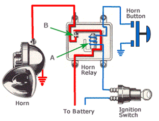
Fig. 19.8: Horn relay system
That path is completed when pushed the horn button. When the button is pushed the ground connection is made, energizing the relay's coil "A". The coil's iron core (in this particular design) pulls down arm, connecting high-current contacts "B". High current then flows from the battery to the horn (the horn is connected to ground because it's mounted to the chassis of the car).
Last modified: Monday, 7 April 2014, 7:47 AM