


 = 0.2680
 …………(14.2)
Site pages
Current course
Participants
General
MODULE - I
MODULE - II
MODULE - III
MODULE - IV
MODULE -V
MODULE - VI
MODULE - VII
MODULE - VIII
MODULE - IX
REFERENCES
LESSON - 14 REVERSIBILITY, IRREVERSIBILITY, CARNOT CYCLE, CARNOT THEOREM
INTRODUCTION
The second law of thermodynamics states that no heat engine can have an efficiency of 100%. Then the question arises if the efficiency of all heat engines is less than 100 per cent, what is the most efficient engine we can have? Before we answer this question, we need to define a reversible process first, which is also called the idealized process.
14.1. REVERSIBLE AND IRREVERSIBLE PROCESSES
14.1.1. Reversible Process:
A process is reversible which once having taken place can be reversed and leaves no trace of change in either the system or surroundings. That is both the system and surroundings could be restored to their original states at the end of a reverse process. This is possible only if the net heat and net work exchange between the system and the surroundings is zero for the combined (initial and reverse) process.
The illustration of reversible process isgiven in Fig. 14.1 where slow movement of a piston during initial process and reverse process due to removal and replacement of small weights in succession, respectively, constitutes a reversible process. This is because the work done by the system on the surrounding during the initial process is equal to the work done on the system by the surroundings during the reverse process. So both the system and surroundings could be restored to their original states at the end of a reverse process.
In the above example the process was carried out in such a way that at every instant during the process, the system remains infinitesimally close to thermodynamic equilibrium state, thus we can say the executed process as a quasi-static process, which was described in ‘Lesson 2’, is a reversible process.
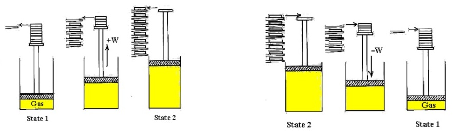
(a): Initial Process from state 1 to state 2 (b): Reverse process from state 2 to state 1
Fig. 14.1. An example of a process that approaches being reversible.
14.1.2. Irreversible process:
Processes that are not reversible are called irreversible processes.
The illustration of an irreversible process is given in Fig. 14.2. Consider a gas at state ‘1’ is kept at high pressure by a piston held with cylinder by a pin.
Initial process: When the pin is removed, the piston is raised and forced abruptly against the stops. The state of the gas is changed to state ‘2’ and negligible amount of work is done by the gas against the weightless piston during process ‘1-2’.
Reverse process: Suppose we restore the system back from state ‘2’ to its original state ‘1’ by compressing the gas until the pin could be again inserted in the piston. Since, the work done on the gas (-W) in this reverse process ‘2-1’ is larger than the negligible work done by the gas in the initial process ‘1-2’, an amount of heat ‘-Q’ must be transferred from the gas to the surroundings during process ‘2-1’ in order that the system has the same internal energy it had originally in state ‘1’.
Results: Thus the system is restored back to its initial state ‘1’, but the surroundings have changed by virtue of the fact that work was required to force the piston down and heat was transferred to the surroundings.
In the above example at every instant during process the system departs finitely from thermodynamic equilibrium state, thus we can say this process as non quasi-static process, which was also described in ‘Lesson 2’, as an irreversible process.

(a): Initial Process from state 1 to state 2 (b): Reverse process from state 2 to state 1
Fig. 14.2. An example of an irreversible process (non quasi-static process)
It should be clear from Fig. 14.1 and Fig.14.2 that a system can be restored to its initial state following a reverse process, regardless of whether the process is reversible or irreversible. But the surroundings is restored back to its initial state only in the case of a reversible process, whereas for irreversible processes, the surroundings usually do some work on the system and therefore does not return to their original state.
14.2. WHICH ARE THE FACTORS THAT CAUSE A PROCESS IRREVERSIBLE?
The factors that cause a process to be irreversible are called irreversibilities. They include friction, unrestrained expansion, heat transfer across a finite temperature difference, mixing of two fluids, electric resistance, inelastic deformation of solids, chemical reactions, and combustion process. The presence of any of these effects renders a process irreversible. A reversible process involves none of these. Some of the frequently encountered factors are discussed briefly below.
14.2.1. Friction
Friction makes a process irreversible.A brief example may clarify this point. Let a block and an inclined plane comprise a system as shown in Fig. 14.3.
Initial process: In the initial process, pull the block up on the inclined plane by lowering weights. During this process, a certain amount of work is done on a block by surroundings to overcome the friction between the block and the plane to increase the potential energy of the block. Also due to friction there is heat loss from the system to the surroundings in the initial process.
Reverse process: Now in the reverse process, the block is restored to its initial position by removing some of the weights, thus allowing the block to slide down the plane itself. Some heat rejection from the system to the surroundings will be required to restore the block to its initial temperature.
Result: Thus the system is restored back to its initial state, but the state of surroundings have changed by virtue of the fact that the net heat and net work transfer of surroundings is not zero for the combined initial and reverse processes. This concludes that friction has rendered the process irreversible.
Another type of frictional effect is that associated with the flow of viscous fluids in pipes and passages and in the movement of bodies through viscous fluids.

Fig. 14.3. Demonstration of the fact that friction makes process irreversible.
14.2.2. Unrestrained expansion
Figure 14.4 shows an example of an unrestrained expansion, in which a gas comprising a system, is separated from a vacuum by a membrane.
Initial process: Consider the initial process ‘1-2’ which occurs when the membrane breaks and the gas fills the entire vessel. There is no heat and work transfer involved between the system and the surrounding during the initial process.
Reverse process: Now in the reverse process, ‘2-1’, the gas is restored to its original state ‘1’ by compressing the gas. Since, there is work done on the gas (-W) in this reverse process, an amount of heat ‘-Q’ must be transferred from the gas to the surroundings during the process ‘2-1’ in order to restore the system to its originally state ‘1’.
Result: Since the system is restored back to its initial state ‘1’, but the work and heat transfer to the surrounding involve in reverse process only, the surroundings are not restored to their initial states, indicating that the unrestrained expansion is an irreversible process.

Fig. 14.4: Demonstration of the fact that unrestrained expansion makes a process irreversible.
|
14.2.3. Heat transfer through a finite temperature difference Consider a high-temperature body and a low-temperature body comprising a system as shown in Fig. 14.5. Initial process: Let during the initial process (Fig. 14.5 (a)) the heat be transferred from the high-temperature body to the low temperature body. Reverse process: The only way in which the system can be restored to its initial state is to provide refrigeration effect (Fig. 14.5 (b)), which requires work from the surroundings. Result: Since the system is restored back to its initial state ‘1’, but because of the work from the surrounding during the reverse process only, the surroundings are not restored to their original states, indicating that the process is irreversible. |
Fig. 14.5. Demonstration of the fact that unrestrained expansion makes a process irreversible. |
14.2.4. Mixing of two different substances
Two different gases are separated by a membrane comprising a system as shown in Fig. 14.6.
Initial process: Let the membrane break and a homogeneous mixture of oxygen and nitrogen fill the entire volume. We can say here that this may be considered as a special case of an unrestrained expansion, for each gas undergoes an unrestrained expansion as it fills the entire volume.
Reverse process: In a reverse process, a certain amount of work is done by the surroundings which is necessary to separate these gases.
Result: Since this work from the surrounding to restore the system to its original state is involved only during the reverse process, there is some change in the surroundings though the system has been restored. The process therefore is irreversible.

Fig. 14.6: Demonstration of the fact that the mixing of two different substances is an irreversible process.
14.2.5. Internal, external and total reversibility
Internally reversible: A process is called internally reversible if no irreversibilities occur within the boundaries of the system during the process. The quasi-static process is an example of internally reversible process because during the initial stage, the process proceeds through a series of thermodynamic equilibrium states, and when the process is reversed to achieve the original state of the system, the process follows the same path of the initial process through exactly the same thermodynamic equilibrium states.
Externally reversible: A process is called externally reversible if no irreversibilities occur outside the system during the process. The process of heat transfer between the reservoir and the system when both are at infinitesimal temperature difference is an example of externally reversible process.
Total reversibility: A process is said to be totally reversible if it comprises no irreversibilities within and outside the system.
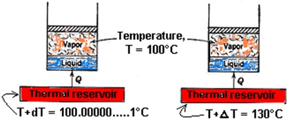
Example :
To clear internally, externally and total reversibility, consider two identical systems in which pure substance comprises a system as shown in Fig. 14.7. Let heat be transferred into both systems and during the heat-transfer process, the temperature of both the systems remain constant at temperature ‘T=100°C’.
|
Let, in the first system heat be transferred from a reservoir at temperature ‘T + dT = 100.00000…..1°C’ which isinfinitesimally higher than temperature ‘T = 100°C’ of the system. Due to small temperature difference, the process of heat transfer between the reservoir and the system is reversible heat-transfer process. In the second system, the heat is transferred from a reservoir at temperature ‘T + ΔT = 130°C’which is higher than temperature ‘T= 100°C’of the system. Due to high temperature difference, the heat transfer between reservoir and system in second case is an irreversible heat-transfer process as explained in Fig. 14.5. However, as far as both the systems are concerned, they pass through exactly the same states during the evaporation process, which we assume, is reversible. Thus, we can say in the first case that the process is both internally and externally reversible i.e. total reversible and in the second case that the process is internally reversible but externally irreversible because the irreversibility occurs outside the system. |
Figure 14.7: Illustration of the difference between an internally and externally reversible process.
|
14.3. WHICH IS BETTER FOR ENGINEERING DEVICES, REVERSIBLE PROCESS OR IRREVERSIBLE PROCESS?
Engineers are interested in reversible processes because work-producing devices such as car engines and gas or steam turbines deliver the maximum work, and work-consuming devices such as compressors, fans, and pumps consume the least work when reversible processes are used instead of irreversible ones.
The above feature of reversible process is explained by an example shown in Fig. 14.8 (a, b) given below. 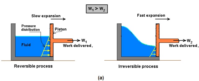
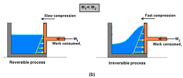
Fig. 14.8: Reversible process (a) delivers the maximum work and (b) consumes the least work
However, we know that reversible process is an ideal process. We may never be able to have reversible process in reality, but we can certainly approach it. The more close a device approaches a reversible process, the more work is delivered by work producing devices and less work required by work consuming devices.
14.4. CARNOT CYCLE
After defining reversible process and considering factors that make processes irreversible let us now answer the question which was asked in the previous section that
“If the efficiency of all heat engines is less than 100 per cent, then what is the most efficient engine we can have?”
Let us answer this question for a heat engine that receives heat from a high-temperature reservoir and rejects heat to a low-temperature reservoir.
Let us assume that this heat engine operates on a cycle in which every process is reversible i.e. reversible cycle. As we know now that a reversible process requires least amount of work and delivers the most, therefore, it is no surprise that a heat engine working on reversible cycle is the most efficient engine.
The reversible cycle on which heat engine works is called the Carnot cycle. Since Carnot cycle is made from reversible processes and we know that a reversible process does not occur in nature, hence the Carnot cycle is also called an ideal cycle.
Examples of heat engine working on Carnot cycle are given below.
14.4.1. Power plant that operates on a Carnot cycle
Consider a power plant as shown in Fig. 14.9 (a) that operates on Carnot cycle. As discussed earlier in ‘Lesson 12’, it is a heat engine in which a pure substance, such as water and steam is used as a working fluid. The power plant works on four reversible processes as shown on p-V diagram in Fig. 14.9 (b).
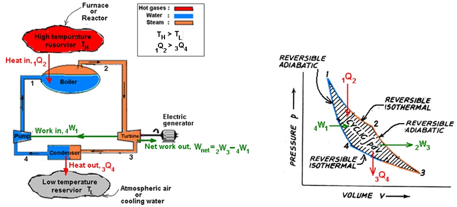
Fig. 14.9. (a) Example of a power plant that operates on a Carnot cycle (b) Carnot cycle on p-V diagram
1st process in the boiler (reversible isothermal process): Heat ‘1Q2’ is transferred from the high-temperature reservoir to the water in the boiler. The temperature of the water is only infinitesimally lower than the temperature of the high-temperature reservoir; consequently it is a reversible heat transfer process. Since the temperature of the reservoir remains constant ‘TH’, that the temperature of the water must remain constant. A change of phase from liquid to vapor at constant pressure in boiler is of course an isothermal process for a pure substance. Therefore, the first process in the Carnot cycle is a reversible isothermal process.
2nd process in the turbine (reversible adiabatic process): In turbine, the process is so fast that it occurs without heat transfer and is therefore adiabatic. Since all processes in the Carnot cycle are reversible, the second process is a reversible adiabatic process. During this process the temperature of the working fluid decreases from high-temperature reservoir to low-temperature reservoir. In turbine the useful work ‘2W3’ is produced.
3rd process in the condenser (reversible isothermal process): In the third process the working fluid flowing in the condenser is completely condensed after rejecting its heat ‘3Q4’ to the low-temperature reservoir. As the temperature ‘TL’ of the working fluid in the condenser is infinitesimally higher than that of low-temperature reservoir, this is a reversible isothermal process.
4th process in the pump (reversible adiabatic process): The fourth process, which completes the cycle, occurs in the pump in which work ‘4W1’ is done on the pump to pump water from condenser pressure to boiler pressure.The pumping work is supplied by the turbine. This processis a reversible adiabatic process in which the temperature of the working fluid increases from the low temperature to the high temperature.
Since the heat engine is reversible, every process could be reversed, in that case it would be a heat pump. Such a heat pump is shown in Figure 14.10. The temperature of the working fluid in the evaporator would be infinitesimally less than the temperature of the low-temperature reservoir, and in the condenser it is infinitesimally higher than that of the high-temperature reservoir. As the heat pump works on a reversible cycle, it is not a surprise that a heat pump working on reversible cycle would be the most efficient pump.

Fig. 14.10. Example of a heat pump that operates on a reversible cycle.
14.4.2. Piston-cylinder arrangement that operates on a Carnot cycle
In another example, consider a piston cylinder arrangement as shown in Fig. 14.11 that works on a Carnot cycle. It is also a heat engine (discussed earlier in ‘Lesson 12’) in which gas is used as the working fluid. In this arrangement, four reversible processes entirely take place within a cylinder. These four reversible processes are mentioned below and are drawn on p-v diagrams in Fig. 14.9 (b).
1st process (reversible isothermal process): A reversible isothermal process ‘1-2’ in which heat is transferred to or from the high-temperature reservoir.
2nd process (reversible adiabatic process): A reversible adiabatic process ‘2-3’ in which the temperature of the working fluid decreases from the high temperature to the low temperature.
3rd process (reversible isothermal process): A reversible isothermal process ‘3-4’ in which heat is transferred to or from the low-temperature reservoir.
4th process (reversible adiabatic process): The fourth process ‘4-1’ which completes the cycle is reversible adiabatic process. In this process the temperature of the working fluid increases from the low temperature to the high temperature.
Here, the main point to be made here is that the Carnot cycle, regardless of the working substance, is always has the same four basic processes.

Fig. 14.11. Example of a gaseous system operating on a Carnot cycle.
14.4.3. Thermal Efficiency of Heat Engine working on Carnot Cycle
Process 1-2 (reversible isothermal process):
pv = c ;


From the energy equation, 1q2 = (u2 – u1) + 1w2 ;
As (u2 – u1) = Cv(T2 – T1) = 0 


Process 2-3 (reversible adiabatic process):
 and 2q3 = 0 ;
From the energy equation, 2q3 = (u3 – u2) + 2w3 ;
2w3 = - (u3 – u2) = (u2 – u3) = Cv(T2 – T3)
Process 3-4 (reversible isothermal process):
pv = c ;
From the energy equation, 3q4 = (u4 – u3) + 3w4 ;
As (u4 – u3) = Cv(T4 – T3) = 0 


Process 4-1 reversible adiabatic process:
and 4q1 = 0 ;
From the energy equation, 4q1 = (u1 – u4) + 4w1 ;
4w1 = − (u1 – u4) = (u4 – u1) = Cv (T4 – T1)
Net heat transfer per kg of working substance per cycle = 


From 1st - law for a cyclic process, 
Net work per kg of working substance per cycle = 
Therefore  ….. ……..(14.1)
Since 2-3 and 4-1 are reversible adiabatic processes,
 and
and 
But T2 = T1 and T3 = T4
Therefore  Using this in equation (14.1)


Heat input, 1q2 = RT1 ln 
Thermal efficiency (ηth) = 


So this is the highest possible thermal efficiency of a heat engine with two given temperatures, ‘TH’ and ‘TL’ and it is not a function of the properties of the working substance.
14.4.4. Two Propositions Regarding the Efficiency of a Carnot Cycle
There are two important propositions regarding the efficiency of a Carnot cycle. These are also called Carnot principles.
First Proposition
It is impossible to construct an engine that operates between two given reservoirs at different temperatures that is more efficient than a reversible engine operating between the same two reservoirs.
Second Proposition
All engines that operate on the Carnot cycle between two given constant-temperature reservoirs have the same efficiency.
These two propositions can be proved by demonstrating that the violation of either of the statements results in the violation of the Second Law of Thermodynamics.
14.4.5. Proof of first and second propositions
Proof of first proposition:
Consider a reversible engine (R.E.) and an irreversible engine (I.E.) operating between the same high temperature and low temperature reservoirs as shown in Fig. 14.12 (a).
In reversible engine: Let the heat transfer from high temperature reservoir to the reversible engine be QH, the heat rejected from it to low temperature reservoir is QL and the work produced by it is WI.E.(= QH − QL ).
In an irreversible engine: Let the heat transfer from the high temperature reservoir to the irreversible engine be QH, the heat rejected from it to low temperature reservoir is QL′, and the work produced by it is WI.E.(= QH − QL′ ).
Let us assume that the irreversible engine (I.E.) operating between the high temperature reservoir and the low temperature reservoir that has a greater efficiency than a reversible engine (R.E.). i.e. η I.E. > η R.E.

Fig. 14.12 (a).
Proof for Carnot's first proposition
As the irreversible engine is more efficient than the reversible engine and , heat input ‘QH’ is the same for both the engines, then we have
WI.E.> WR.E.
or (QH − QL′ ) > (QH − QL)
it follows that QL' < QL.
Now reverse the reversible engine so that it works as a heat pump by taking work input WR.E. (= QH-QL) from the irreversible engine as shown in Fig. 14.12 (b). By giving work input to the reversible engine, the irreversible engine still delivers the net work (Wnet = WI.E. – WR.E. = QL – QL′).
However, if we consider the two engines and the high-temperature reservoir as a system, as indicated in Fig. 14.12 (b), then we have a system that operates in a cycle, exchanging heat with a single reservoir, and does a certain amount of work as indicated in Fig. 14.12 (c). However, this would constitute the violation of the Second law and we conclude that our initial assumption “that the irreversible engine is more efficient than the reversible engine” is incorrect.
Hence, ηR.E. ≥ ηI.E.
So, we conclude that we cannot have an irreversible engine which is more efficient than a reversible engine operating between the same two reservoirs.
|
|
|
|
(b) |
(c) |
Fig. 14.12. Demonstration of the fact that the Carnot cycle is the most efficient cycle operating between two fixed temperature reservoirs.
Proof of Second first proposition:
The second Carnot proposition can also be proved in a similar way as the previous proposition has been proved.
To start with, let us replace the irreversible engine (I.R.) of the previous proof with the reversible engine (R.E.)1 and then assume that replaced reversible engine (R.E.)1 is more efficient than another reversible engine (R.E.)2 operating between the same two reservoirs i.e (R.E.)1 delivers more work than (R.E.)2 as shown in Fig. 14.13.

Fig. 14.13. One reversible engine is more efficient than another reversible engine.
By following through same the same line of reasoning as discussed in the previous proof, and reversing the reversible engine ‘(R.E.)2’ so that it works as a heat pump by taking work input ‘W(R.E.)2’ from the more efficient reversible engine ‘W(R.E.)1’ as shown in Fig. 14.13 (a), we end up having a system that produces a net amount of work while exchanging heat with a single reservoir (Fig. 14.13 (b)), which is a violation of Second law.
So, we conclude that no reversible heat engine can be more efficient than another reversible engine operating between the same two reservoirs.
|
|
|
|
|
(a) |
(b) |
|
Fig. 14.13. Demonstration of the fact that all reversible engines operating between the same two reservoirs have the same efficiency.
Example 14.1: An inventor claims to have heat engine which is capable of developing 9 kW while working between the temperature limits of 30oC and - 40°C.It receives only 1000 kJ/min of heat. Discuss the possibility of the claim.
Solution:
Given: Net work, W = 9kW; QH = 1000 kJ/min; TH = 30 + 273 = 303K; TL = (−40 +273) = 233K
Determine the possibility of claim:
Formula: Claim is possible if ηclaimed ≤ ηmax
Finding unknown, ηmax:
By Carnot theorem, the maximum thermal efficiency for a reversible engine is given by
ηmax =  = 0.422 = 42.2%
Finding unknown, ηclaim:
The efficiency claimed is given by
ηclaimed =  = 0.540 or 54%
Answer: ηclaimed > ηmax , Thus the inventor’s claim is false
14.5. THERMODYNAMIC SCALE OF TEMPERATURE
It should be noted that we have not considered an absolute scale of temperature, usually referred to as Thermodynamic scale of temperature, when we had defined Zeroth law and temperature scales in Lesson 4. This is because the possibility of an absolute scale arises from the Second law of thermodynamics.
As we have now defined the Second law of thermodynamics, the absolute temperature scale independent of any thermometric substance on the basis of the Second law of thermodynamics is defined which is explained as under:
|
Let a heat engine operating on the Carnot cycle receive heat from a high temperature reservoir maintained at steam point and it rejects heat to a low temperature reservoir maintained at ice point as shown in Fig. 14.14. If the efficiency of such an engine could be measured, it would be found to be 26.80 percent. Therefore, the thermal efficiency of Carnot cycle, η carnot = or = or |
Fig. 14.14. Heat engine used to develop the thermodynamic scale of temperature. |
In order to assign values of absolute temperatures, the second relation between Tsteam and Tice must be required.
In order to define an absolute temperature scale related to Centigrade scale known as Kelvin scale (designated by K), we use the second relation that the difference between ice point and the steam point is 100 degree, just as that for Centigrade scale.
Therefore, we can write
Tsteam point – Tice point = 100 ….…...…(14.3)
Solving equations (14.2) and (14.3) we find
Tsteam point = 373.15 K Tice point = 273.15 K
It follows that the temperature of Centigrade and Kelvin scale differ by a constant 273.15.
Therefore, we can write absolute temperature of Centigrade scale as,
T (°K) = t (°C) + 273.15
Last modified: Tuesday, 10 September 2013, 4:56 AM