

Site pages
Current course
Participants
General
MODULE - I
MODULE - II
MODULE - III
MODULE - IV
MODULE -V
MODULE - VI
MODULE - VII
MODULE - VIII
MODULE - IX
REFERENCES
LESSON - 30 BOILER ACCESSORIES
The boiler accessories are auxiliary devices which are installed either inside or outside the boiler. The boiler accessories are used to increase the efficiency of the boiler and for proper functioning of boiler. The following accessories are generally used in the boiler:-
(a) Economiser
(b) Air preheater
(c) Superheater
(d) Feed pump
(i) Duplex
(ii) Injector
(e) Steam trap
(f) Steam separator
(g) Pressure reducing valve.
30.1. Relative Position of Superheater, Economiser and Air Preheater
The relative positions of the air pre-heater, economiser and superheater are shown in Fig. 30.1.
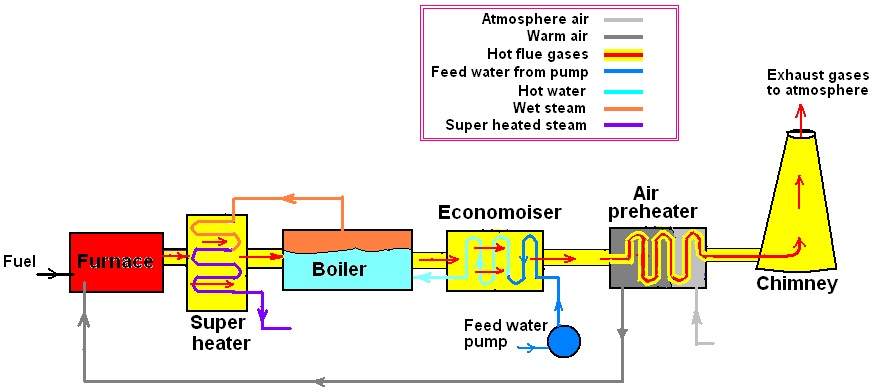
Fig. 30.1. Relative Position of Superheater, Economiser and Air Pre-heater.
30.2. Economiser
Function: The function of the economiser is to extract some heat which is carried away by the flue gases up in the chimney or stack and utilize it for pre-heating the feed water supplied to the boiler.
Location: It is placed in the path of the flue gases in between the exit from the boiler and entry into air preheater/chimney (Fig 30.1 and Fig 30.2).
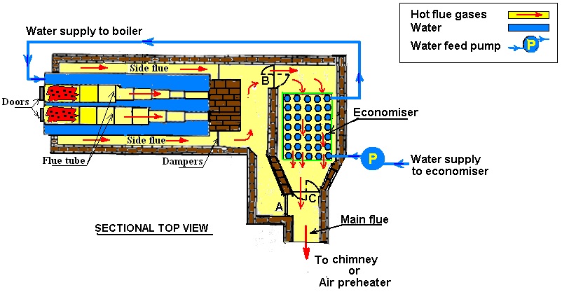
Fig. 30.2. Lancashire boilers fitted with an economiser
Why this device is called Economiser instead of Feed Water Pre-heater?
As the temperature of feed water is raised before it is supplied in boiler with the use of an economiser, water in the boiler needs less heat for its conversion into steam. This results in a fuel saving which improves the economy of the boiler plant. As the recovery of additional heat improves the economy of the boiler plant, so its name is given as economizer instead of feed water pre-heater.
The percentage of saving in fuel consumption is given by
S = 
Where, S = percentage saving in fuel consumption
t2 = temperature of feed water at the outlet of economizer, °C
t1 = temperature of feed water at the inlet of economizer, °C
hg = enthalpy of dry steam at boiler pressure, kJ/kg
hsub,1 = enthalpy of water at t1 °C, kJ/kg
Cp = specific heat of water, kJ/kgK
Construction:
The Green’s economizer used with the stationary boilers is shown in Fig. 30.3 along with its construction details. It consists of a group of vertical cast iron tubes which are fitted between top and bottom headers. For safety against high pressure, a safety valve is mounted on the top of the header. Like boiler, it has blow down valve fitted at the bottom to discharge sediments collected at the bottom of economizer. Scrapers are provided on the tubes to remove the soot of flue gas deposited on the tubes of the economiser. The soot thus removed from the tubes is collected in a chamber provided at the bottom of economizer. The two stop valves, one at the bottom header and other at the top header, are provided to stop or allow water into and out of the economizer, respectively.
Operation:
The feed water from the feed pump first enters into the bottom header of economizer before it enters into the boiler. From the bottom header the water then passes through the vertical tubes and reaches into the top header, from where it finally leads into the boiler. At the same time the flue gas moves around the tubes and gives off their heat to the water flowing inside the vertical tubes and water is thereby heated in the economizer.
While economizer in operation of water heating, the scrapers provided on the tubes are moved up and down continuously with the help of chain and gear arrangement so that soot deposited on the pipes may be removed and maximum efficiency of the economizer may be achieved as the soot deposit on pipes reduce the heat transfer to water.

Fig. 30.3. Green’s Economiser
A by-pass arrangement as shown in Fig. 30.4 is provided to isolate the economiser when it is not required or when it is to be cleaned or repaired. When the economiser is in service, the damper A is closed while the dampers B and C are opened. When the economiser is not in service then the dampers B and C is closed and the damper A should be opened.

Fig. 30.4. A by-pass arrangement of an economiser in Lancashire boilers
Advantages of an economiser:
(i) Increase in thermal efficiency of the boiler plant by utilizing waste heat, saving in fuel.
(ii) Hot feed water causes increase in evaporative-capacity.
(iii) Longer life of the boiler as this reduces the temperature difference between different parts of the boiler
(iv) A large quantity of scale forming impurities may be removed by precipitation due to pre-heating the feed water.
(v) Dissolved gases such as air or CO2 may also be removed by pre-heating the feed water, reducing corrosion and pitting.
Disadvantage:
It reduces natural draft as it obstructs the passage of flue gases.
Problem 30.1: Calculate the percentage of fuel saving by installing an economizer with a boiler if the steam leaves the boiler dry and saturated at 13 bar. The feed water enters the economizer at 40°C and leaves at 125°C.
Solution:
Given: Steam pressure in boiler = p = 13 bar
From steam tables, for steam at pressure, p = 13 bar
ts = 191.60°C. hf = 814.59 hg = 2785.7 kJ/kg
The feed water enters the economizer at temperature, ti = 40°C
The feed water leaves the economizer at temperature, te = 125°C.
Determine the percentage of fuel saving by installing an economizer with a boiler:
Formula: Saving in fuel = ![]() x100
x100
Finding unknown,
Heat saved by pre-heating 1 kg of feed water in economizer,
= m Cp(te –ti) = 1 x 4.18 x (125 - 40) = 355.3 kJ/kg
Heat required to convert 1 kg of water at 40°C to dry saturated steam at 13 bar
= hg – hsub = m Cp (ts –ti) + (hg - hf)
= 1 x 4.18 x (191.60 - 40) + (2785.7 - 814.59)
= 633.69+1971.11 = 2604.8 kJ/kg
Answer : Saving in fuel = ![]() x 100
x 100
 × 100 = 13.6%
30.3. Air Preheater
Function: Like economizer, an air preheater also recovers some portion of the waste heat of the flue/chimney gases and utilizes it for preheating of air supplied to the combustion chamber of the boiler.
Location: Air preheater is usually placed after the economiser and before the gases enters the chimney as shown in Fig 30.1.
Construction and operation:
Air preheaters can be classified as tubular type, plate type and regenerative type:
|
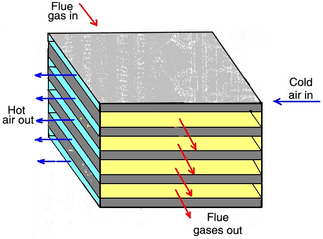
(i) Tubular type: A tubular type commonly used in smaller boiler plants is shown in Fig. 30.5. The hot gases are passed through the tubes and air is forced to flow over the tubes. To increase the period of contact between the air and hot surface so that air is effectively heated, air is forced to deflect by using baffles and compelled to move in a zigzag path for a number of times. The soot and other material carried with gases are collected in the hopper at the bottom and removed periodically through the soot gate. |
Fig. 30.5. Tubular Air Preheaters
|
|
(ii) Plate type: In this preheater, alternative gas and air passages are formed between closely spaced parallel plates. The air flows through the alternate spaces of these parallel plates and flue gas passes through the remaining passages as shown in Fig. 30.6. |
Fig. 30.6. Plate air-preheater
|
(iii) Regenerative type: The hot flue gas and air are made to flow alternatively through the same path consisting wire mesh as shown in Fig. 30.7. The hot flue gasses are made to pass through wire mesh by opening valves 1 & 4 and closing valves 2 & 3. While passing through wire mesh, the hot flue gasses reject and store their heat into wire mesh. In the alternate pass, when the atmosphere air is passed through wire mesh by opening valves 2 & 3 and closing valves 1 & 4, it receives heat from wire mesh and as a result the air gets heated.
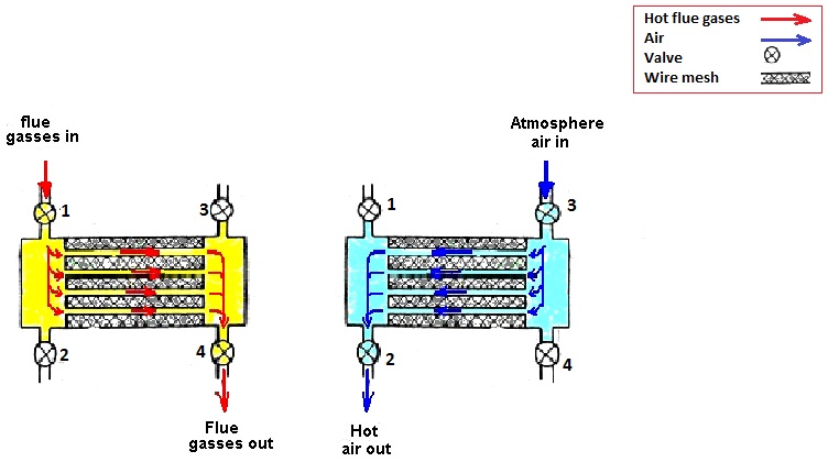
Fig. 30.7. Regenerative-preheater
Advantages of preheating of air:
(1) Waste heat from the flue gases is recovered for heating air and causes a fuel saving of about 1.5% for each 100°C drop in gas temperature.
(2) Inferior grades of coal can be burnt efficiently with preheated air.
(3) Less excessive air is required to burn fuel and thus cost of producing draught will be less.
(4) Combustion can be more efficient and an intense flame can be achieved in the furnace. This increases the evaporation rate of the boiler.
Disadvantages:
(i) Increase in the capital and running cost of the preheater as induced draft fan for removing gases and forced fan for forcing cold air through the air preheater are used.
Problem 30.2: The fuel used in a boiler is having a calorific value of 25120 kJ/kg. The temperature of the gas leaving the economizer chamber is 260°C and is reduced to 150°C while leaving the pre-heater chamber. If 18 kg of air is supplied per kg of coal burnt and the efficiency of pre-heater is 80% determine (a) the percentage saving of heat of coal in the pre-heater, (b) the temperature of air leaving the pre-heater if the initial temperature of air is 27°C. Take Cp of air and flue gases equal to 1.05 kJ/kg.
Solution:
Given: Calorific value of fuel used in a boiler = 25120 kJ/kg
Temperature of the gas leaving the economiser and entering pre-heater, tg,i= 260°C
Temperature of the gas leaving pre-heater, tg,e = 150°C
Temperature of the air entering pre-heater, ta,i = 27°C
Efficiency of pre-heater, ηcp = 80%
Mass of air supplied to boiler furnace per kg of coal burnt = 18 kg
Cp of air and flue gases = 1.05 kJ/kg.
(a) Determine the percentage saving of heat of coal in the pre-heater:
Formula: Percentage of saving of heat of coal in the pre-heater
= ![]()
Finding unknown,
Heat transferred to air in the pre-heater per kg of coal burnt = mf .Cp .(te-ti). ηcp
Finding unknown, mf ;
Mass of flue gases/kg of coal, mf = mass of coal + mass of air
=18 + 1 = 19 kg
Therefore, heat transferred to air in the pre-heater = mf .Cp .(tg,e-tg,i). ηcp
= 19 x 1.05 x (260 - 150) x 0.8
= 1755.6 kJ/kg
Answer: Percentage of saving of heat of coal in the pre-heater
= ![]()
=  = 6.988%
(b) Determine the temperature of air leaving the pre-heater
Let ta,e °C be the temperature of air leaving the preheater.
Formula: Heat transferred by gas in the pre-heater = Heat gain by air
= ma .Cp . (ta,e – ta,i)
Answer: Heat transferred by gas to air in the pre-heater = ma .Cp . (ta,e – ta,i)
1755.6 = 18 x 1.05 (ta,e - 27)
or ta,e = 119.888°C
30.4. Steam superheater
Function: In superheaters, the wet or saturated dry steam is superheated by increasing steam temperature above its saturation temperature.
Location: The superheater is installed in the path of flue gases after the furnace as shown in Fig 30.1. Sometimes, for bigger boilers, the superheater may be placed in an independent fire furnace.
Construction and operation:
It consists of a set of tubes through which wet or saturated dry steam flows and hot combustion gases pass around these tubes. By this way, the wet or saturated dry steam takes heat from the flue gases and become superheated.
|
Classification of Superheaters: According to the mode of heat reception: (i) Convective superheaters, (ii) Radiant superheaters and (ii) Combination superheaters as shown in Fig. 30.8. (i) Convective superheaters: In the convective superheaters, the superheaters are placed between or near the water tubes where the superheater tubes receive heat by convection from combustion gases. (ii) Radiant type superheaters: In the radiation superheaters, the superheaters are placed in the walls of the furnace of a steam boiler where the superheater tubes receive heat by direct radiation from fire and re-radiation from refractory walls. (iii) Combination type: In combined superheaters, the steam first enters the radiant superheater and then the convective superheater. In this heat of combustion is transferred to the superheater tubes by radiation and then convection. |
Fig. 30.8. Position of Convective, radiant and combination superheaters. |
According to the movement of gases and steam:
There types are
(i) Parallel flow,
(ii) Counterflow and
(iii) Combined flow
as shown in Fig. 30.9 (a,b,c).
(i) Parallel flow superheater: The hot flue gases and wet steam flows in the same direction.
(ii) Counter flow superheater: The hot flue gases and wet steam flows in opposite direction.
(iii) Combined flow superheater: The hot flue gases and wet steam first flows in opposite direction and then in the same direction.
From the above classification, the counter flow superheater is commonly used because of its smaller size, lighter in weight and maximum efficiency.

Fig. 30.9. (a) Parallel flow, (b) Counter flow and (c) Combined flow superheaters
According to the arrangement of the superheater tubes:
(i) Overdeck. This is placed in the space over the water tubes as shown in Babcock & Wilcox boiler in Fig. 28.3.
(ii) Interdeck. This is placed between the water tubes which are located near the furnace.
(iii) Intertubes. This is placed between bank or row of water tubes.
Advantages:
The following benefits are gained by superheating steam in superheaters:
(1) It decreases the specific steam consumption of steam engines or turbines.
(2) It decreases the condensation losses in the steam pipes and steam engine cylinder.
(3) It eliminates the erosion of the turbine blades.
(4) The efficiency of the steam plant is increases.
30.5. Feed Pumps
Function:
The function of feed pump is to pump the feed water into the boiler against the pressure of boiler.
Classification of feed pumps:
The three types of feed pumps commonly used are
(i) Rotary,
(ii) Reciprocating and
(iii) Injector.
(i) Rotary pumps: This type of pump is used when a large amount of feed water is to be supplied to the boiler. These are generally high speed centrifugal type driven by either electric motor or small steam turbine which is run by the steam from the same boiler to which water is to be fed.
(ii) Reciprocating pumps: The Duplex feed pump shown in Fig 30.10 is a common type of reciprocating pump which is used for medium size boilers.
The construction and operation of Duplex feed pump is described below:
It is a double acting feed pump. It consists of two pumps, namely water pump and steam pump, mounted side by side. Both pumps have their own cylinder. The piston of both cylinders are connected to its own piston rod which is finally connected to a common cross head so that the steam pump serves as driver of the water pump due to the expansion of steam in the steam cylinder. In the steam pump, D-sliding valve, driven by common cross head of two cylinders, is used to control the admission and exhaust of steam in steam cylinder whereas in water pump automatic operated suction and delivery valves are used for intake and discharge of feed water in water cylinder. For continuous supply of feed water at high pressure, the water pump is continuously run by the steam pump with the continuous supply of steam into steam cylinder from the same boiler to which water is to be fed.
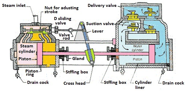
Fig. 30.10. Duplex feed pump
(iii) Injector: The injector is another type of feed pump in which the energy of steam jet is used for feeding water into the boiler. It is suitable of small boilers or where space is not available for the installation of a feed of feed pump as in the case of Locomotive boiler. Its maintenance cost is less and it is thermally very efficient as the steam required to operate the injector is returned to the boiler.
30.6. Steam Trap
Function: The function of steam trap is to drain off partial condensed water from steam pipes without allowing the steam to escape through it.
Location: It is arranged in the steam pipe near the engine or the turbine.
Types of steam traps:
The steam trap are of two types:
(i) Bucket or float type
(ii) Thermal expansion type.
|
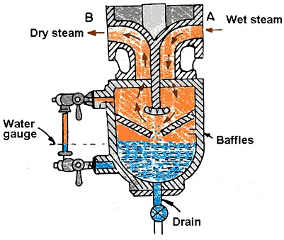
30.7. Steam Separator Function: The function of a steam separator is to separate suspended water particles carried by steam on its way from the boiler to the engine or turbine without allowing the steam to escape through it. Location: It is installed in the main steam pipe very near to the engine or turbine. Construction and operation: Refer Fig. 30.11. The steam from the boiler enters the steam separator through a flange ‘A’ and flows downward. During its passage down, it strikes the baffles and changes its direction. While changing direction, the suspended water partials in steam fall to the bottom of the separator due to greater inertia and the dry steam deflected up comes out through the flange ‘B’. The water collected at the bottom is drained out by the drain arrangement. A water gauge glass is fitted in the separator to see the level of water in the separator. |
Fig. 30.11. Steam Separator |
|
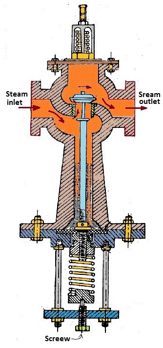
30.8. Pressure Reducing Valve Function: The function of a pressure reducing valve is to supply steam at constant pressure on its delivery side by throttling inconsistent supply of steam from the boiler on its inlet side. Location: The pressure reducing valves are installed in steam supply pipe to supply constant pressure steam lower than the boiler pressure required by the prime movers. Construction and operation: Fig. 30.12 shows a pressure reducing valve. The high pressure steam from the boiler enters the steam inlet flange. After entering into pressure reducing valve, the steam passes through the throttle valve where it is throttled to low required pressure and hence the steam at the outlet of pressure reducing valve is achieved at reduced pressure. To achieve required reduced pressure at the outlet of the valve, the throttled valve actuated by spring and valve rod mechanism is adjusted accordingly by the adjusting screw F.
|
Fig. 30.12. Pressure reducing valve |
Last modified: Wednesday, 11 September 2013, 5:14 AM