Site pages
Current course
Participants
General
MODULE 1.
MODULE 2.
MODULE 3.
MODULE 4.
MODULE 5.
MODULE 6.
MODULE 7.
MODULE 8.
MODULE 9.
MODULE 10.
MODULE 11.
MODULE 12.
LESSON 4. Stresses on structures
4.1 INTRODUCTION
When a structural member is loaded, deformation of the member takes place and resistance is set up against deformation. This resistance to deformation is known as stress. The stress is defined as force per unit cross sectional area. The nature of stress developed in the structural member depends upon nature of loading on the member.
4.2 TYPES OF LOADS
The following are the various types of stresses:
-
Axial stress (direct stress) : i. Tensile stress ii. Compressive stress
-
Bearing stress
-
Bending stress
-
Shear stress
A member may be subjected to combined direct and bending stress. Such stress is known as combined stress. The tensile stresses are taken as positive and compressive stress as negative. This sign convention for stresses is convenient as a structural member elongates on application of tensile load and shortens on application of compressive load.
4.3 STRESS-STRAIN RELATIONSHIP FOR MILD STEEL
When a mild steel bar is subjected to a tensile load, it elongates. The elongation per unit length is known as strain. The stress is proportional to stain within limit of proportionality. The stress-strain relationship for mild steel can be studied by plotting stress-strain curve. The stress and load may be plotted on y-axis and strain may be plotted on x-axis as shown in Fig. 4.1.
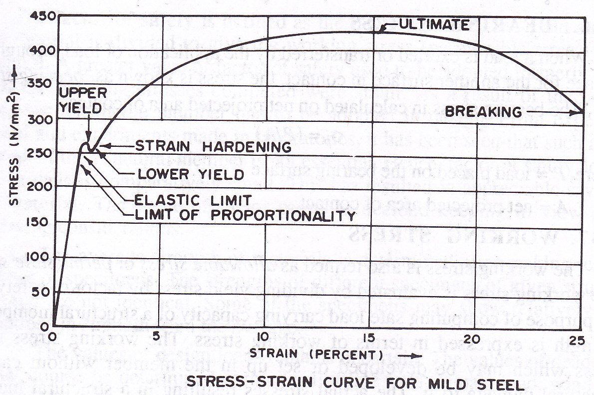
Fig. 4.1 Stress-strain curve
When the tensile load increases with increase in strain, stress-strain curve follows a straight line relationship up to ‘Limit of proportionality’. The limit of proportionality is defined as stress beyond which straight line relationship ceases between stress and strain. Beyond the limit of proportionality stress approaches the elastic limit. The elastic limit is defined as the maximum stress up to which a specimen regains its original length on the removal of the applied load. There is hardly any distinct difference in the position of limit of proportionality and elastic limit. Practically, position of limit of proportionality coincides with the elastic limit. When the specimen is loaded beyond the elastic limit, the specimen does not resume its original length on the removal of applied load and a little strain is left in the specimen. This little strain is known as residual strain or permanent set.
When the tensile load further increases the stress reaches ‘yield stress’ and material starts yielding. The stress-strain curve suddenly falls showing a decrease in stress. The distinct position from where sudden fall of curve occurs marks the upper yield point and the position up to which fall of curve occurs is known as lower yield point. The material stretches suddenly at constant stress. The adjustment of stress takes place in the elements of material in between upper yield point and lower yield point. On further increase of load, stress increases with the increase of strain. However, strain increases more rapidly. Finally the load reaches the value of ‘ultimate load’. The ultimate load is defined as maximum load, which can be placed prior to the breaking of specimen. The stress corresponding to the ultimate load is known as ‘ultimate stress’. The stress-strain curve suddenly falls with rapid increase in strain and specimen breaks. The load corresponding to breaking position is known as ‘breaking load’. The cross-section of specimen decreases. If actual breaking stress is computed on the basis of decreased cross-sectional area, the breaking stress will be found to be more than the ultimate stress.
The boundaries of grains of mild steel are composed of brittle material. This forms a rigid skeleton. The rigid skeleton prevents plastic deformation of the grains at low stress and shows upper yield point in stress-strain curve. At upper yield point, this rigid skeleton breaks down. As a result of this, the stress in material drops down without elongation from upper yield point to lower yield point. This is followed by sudden stretching of the material at constant stress from lower yield point up to strain hardening.
4.4 TENSILE STRESS
When a structural member is subjected to direct axial tensile load, the stress is known as tensile stress (σat). The tensile stress is calculated on net cross-sectional area of the member:
σat = (Pt/An)
Where Pt is the direct axial tensile load and An is the net cross-sectional area of the member.
4.5 COMPRESSIVE STRESS
When a structural member is subjected to direct axial compressive load, the stress is known as compressive stress (σac). The compressive stress is calculated on gross cross-sectional area of the member
σac = (Pc/Ag)
Where Pc is the direct axial compressive load and Ag is the gross cross-sectional area of the member
4.6 BEARING STRESS
When a load is exerted or transferred by the application of load through one surface for the another surface in contact, the stress is known as ‘bearing stress’(σb). the bearing stress is calculated on net projected area of contact
σb = (P/A)
Where P is load placed on the bearing suface and A is the net projected area of contact.
4.7 WORKING STRESS
The working stress is also termed as allowable stress or permissible stress. The working stress is evaluated by dividing yield stress by factor of safety. For the purpose of computing safe load carrying capacity of a structural member, its strength is expressed in terms of working stress. The working stress is the stress which may be developed or set up in the member without causing structural damage to it. The actual stress resulting in a structural member from design loads should not exceed working stresses. This ensures the safety of structural member. The maximum working stresses are adopted from IS : 800-1984.
4.8 INCREASE IN PERMISSIBLE STRESS
A structure may be subjected to the different combinations of loads. These loads in combinations do not act for long period. Most of the national codes allow some increase in permissible stresses. Increase in permissible stresses as per IS : 800 is taken as follows:
-
When the effect of wind or seismic load is taken in to account, the permissible stress in steel are increased by 33⅓ percent.
-
For rivets, bolts and tension rods, the permissible stresses are increased by 25 per cent, when the effect of wind or seismic load is taken in to account.
The increased values of permissible stress must not exceed yield stress of the material.
4.9 FACTOR OF SAFETY
The factor of safety is defined as the factor by which the yield stress of the material is divided to give the working stress (permissible stress) in the material. A greater value of factor of safety results a larger cross-section of the member had to be adopted in design. If the factor of safety is comparatively small, results in appreciable saving in the material. The value of factor of safety is decided keeping in view of the following considerations.
-
The average strength of materials is determined after making test on number of specimens
-
The value of design loads remains uncertain
-
The values of internal forces in many structures depend upon methods of analysis
-
During fabrication, structural steel is subjected to different operations which causes the structural element are subjected to uncertain erection stress
-
The variations in temperatures and settlement of supports are uncertain
-
The failure of some small or some elements of a structure is less serious and less disastrous than the failure of large structure or main element of a structure
4.10 METHODS OF DESIGN
The following methods may be employed for the design of the steel frame work:
-
Simple design
-
Semi-rigid design
-
Fully rigid design and
-
Plastic design
4.10.1 Simple Design
This method is based on elastic theory and applies to structure in which the end connections between members are such that they will not develop restraint moments adversely affecting the members and the structures as a whole and in consequence the structure may be assumed to be pin jointed.
4.10.2 Semi-rigid design
This method permits a reduction in the maximum bending moment in beams suitably connected to their supports, so as to provide a degree of direction fixity. In the case of triangulated frames, it permits rotation account being taken of the rigidity of the connections and the moment of interaction of members. In cases where this method of design is employed, it is ensured that the assumed partial fixity is available and calculations based on general or particular experimental evidence shall be made to show that the stresses in any part of the structure are not in excess of those laid down in IS : 800-1984.
4.10.3 Fully rigid design
This method assumes that the end connections are fully rigid and are capable of transmitting moments and shears. It is also assumed that the angle between the members at the joint does not change, when it is subjected to loading. This method gives economy in the weight of steel used when applied in appropriate cases. The end connections of members of the frame shall have sufficient rigidity to hold virtually unchanged original angles between such members and the members they connect. The design should be based on accurate methods of elastic analysis and calculated stresses shall not exceed permissible stress.
4.10.4 Plastic design
The method of plastic analysis and design is recently (1935) developed and all the problems related to this are not yet decided. In this method, the structural usefulness of the material is limited up to ultimate load. This method has its main application in the analysis and design of statically indeterminate framed structures. This method provides striking economy as regards the weight of the steel. This method provides the margin of safety in terms of load factor which one is not less than provided in elastic design. A load factor of 1.85 is adopted for dead load plus live load and 1.40 is adopted for dead load, live load and wind or earthquake forces. The deflection under working load should not exceed the limits prescribed in IS : 800-1984.
4.11 STABILITY OF STRUCTURE
According to the stability requirement, the stability of a structure as a whole against overturning is ensured so that the restoring moment is greater than the maximum overturning moment. The restoring moment shall be not less than the sum of 1.2 times the maximum overturning moment due to the characteristic dead load and 1.4 times the maximum overturning moment due to characteristic imposed loads.
The structure should have adequate factor of safety against sliding due to the most adverse combination of the applied loads. The structure shall have a factor of safety against sliding not less than 1.4 under the most adverse combination of the applied characteristic forces. In case only dead loads are acting, only 0.9 times the characteristic dead load shall be taken in to account.
To ensure stability at all times, account shall be taken of probable variations in dead load during construction, repair or other temporary measures. The wind and seismic loading shall be treated as imposed loading. In designing the framework of a building, provisions shall be made by adequate moment connections or by a system of bracings to effectively transmit all the horizontal forces to the foundations.
Last modified: Friday, 1 November 2013, 9:19 AM