Site pages
Current course
Participants
General
MODULE 1.
MODULE 2.
MODULE 3.
MODULE 4.
MODULE 5.
MODULE 6.
MODULE 7.
MODULE 8.
MODULE 9.
MODULE 10.
MODULE 11.
MODULE 12.
LESSON 13. Steel Beams
13.1 INTRODUCTION
A beam is defined as a structural member subjected to transverse loads. The plane of transverse load is parallel to the plane of symmetry of the cross-section of the beam and it passes through the shear centre, so that the simple bending occurs. The transverse loads produce bending moments and shear forces in the beams at all the section of the beam.
The term joist is use for beams of light sections. Joist support floor construction; they do not support other beams. The term subsidiary beam or secondary beam is also used for the beams supporting floor construction. Main beams are the supporting joists for subsidiary beams. These are called floor beams in buildings. The term girder is most commonly used in buildings. Any major beam in a structure is known as a girder.
In the roof trusses, horizontal beams spanning between the two adjacent trusses are known as purlins. The beams resting on the purlins are known as common rafter or simply rafters. In the buildings the beams spanning over the doors, windows and other openings in the walls are known as lintels. The beams at the outside wall of a building, supporting its share of the floor and also wall upto the floor above it are known as spandrel beams. The beams framed to two beams at right angles to it and usually supporting joists on one side of it; used at openings such as stair wells are known as headers. The beams supporting the headers are termed as trimmers. The beams supporting the stair steps are called as stringers.
In the brigde floors, the longitudinal beams supported by the floor beams are also called as stringers. In the mill buildings, the horizontal beams spanning between the wall columns and supporting wall covering are called as girts. The beams are also called simply supported, overhanging cantilever, fixed and continuous depending upon nature of supports and conditions.
13.2 ROLLED STEEL SECTIONS USED AS BEAMS
The rolled steel I-sections, channel sections, angle sections, tee-sections, flat sections and bars as shown in Fig. 13.1 are the regular sections, which are used as beams. The rolled steel I-sections as shown in Fig. 13.1.A are most commonly used as the beams and as such thses sections are also termed as beam sections. The rolled steel I-sections are symmetrical sections. In these sections more material is placed near top and bottom faces, i.e., in the flanges as compared to the web portion. The rolled steel I-sections provide large moment of inertia about xx-axis with less cross sectional area. The rolled steel I-sections provide large moment of resistance as compared to the other sections and as such these are most efficient and economical beam sections. The rolled steel wide flange beams as shown in Fig. 13.1.B provide additional desirable features. As the name indicates, the flanges of the sections are wide. These sections provide greater lateral stability and facilitate the connections of flanges to other members. I-sections and wide flange beam sections have excellent strength.
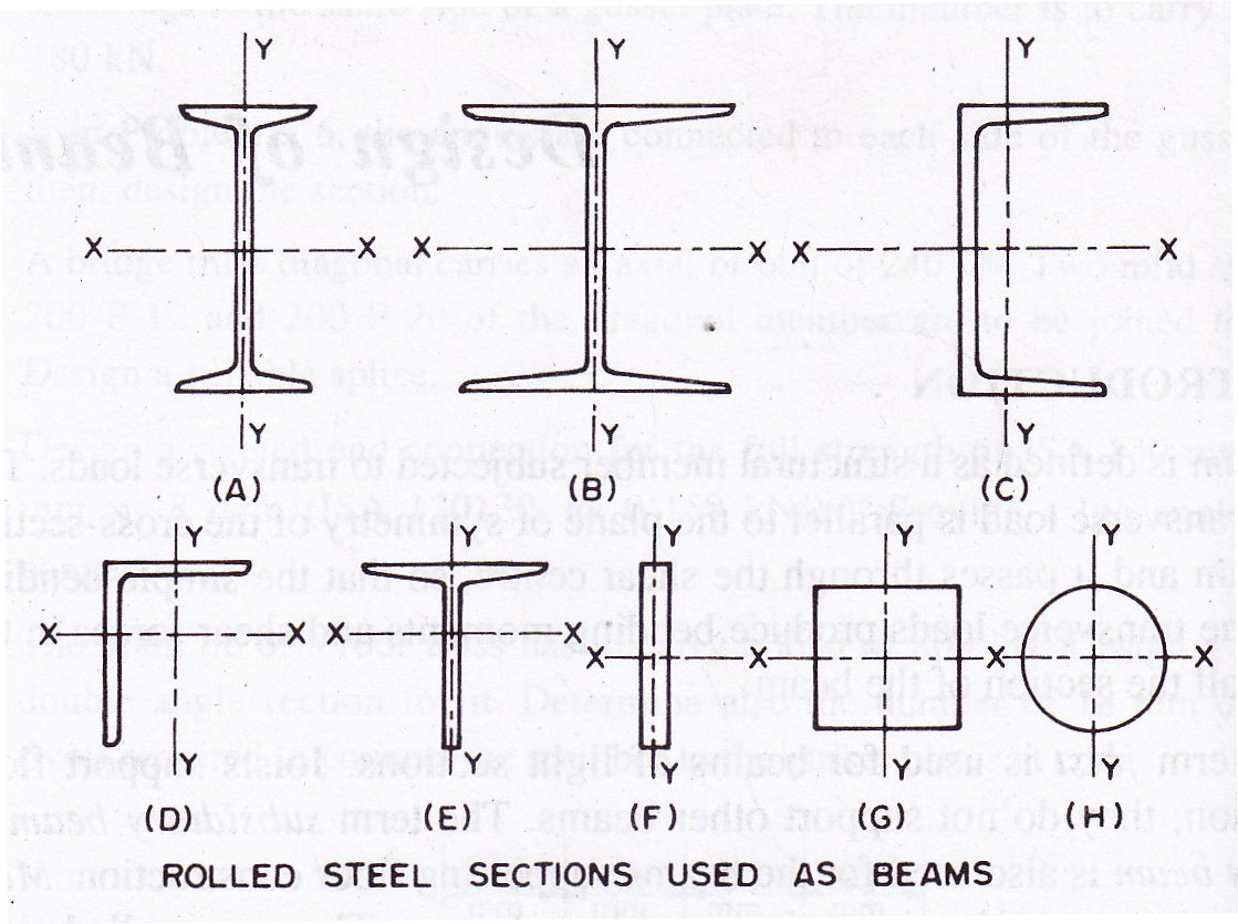
The rolled steel channel sections as shown in Fig. 13.1.C are used as purlins and other small structural member. The channel sections have reasonably good lateral strength and poor lateral stability. The channel sections are unsymmetrical sections about yy-axis. When the channel sections are loaded and supported by vertical forces passing through the centroid of the channel, then the channel sections bend and twist if these are laterally unsupported, except for the special case, wherein the loads act normal to the plane of web, causing bending in the weakest direction. The rolled steel angle sections as shown in Fig. 13.1.D are also used as purlins and so other small structural members. The angle sections act as unsymmetrical sections about both xx-axis and yy-axis.
The rolled steel tee-sections as shown in Fig. 13.1.E are used as beams in the rectangular water tanks. The angles and tee-sections are used for light loads. The rolled steel flats and bars as shown in 13.1.F, G and H are very rarely used. These sections are weak in resisting bending. Most commonly the beams are loaded in the direction perpendicular to xx-axis, so that the bending of beams occurs about strong and xx-axis becomes neutral axis. The beams are very rarely loaded in the direction perpendicular to yy-axis. In such cases, yy-axis becomes neutral axis.
In cases of bending of the beams about one axis, the load is considered to be applied through the shear centre of the beam sections. In case, the loading passes through the shear centre, the section may be analyzed for simple bending and shear. The shear centre for the beam section is at the centre of area and this load position produces simple bending about either axis. When the load does not pass through the shear centre as in channels, angles and some built-up sections, a torsional moment is produced along with the bending moment and both are considered to avoid over stressing of the member. For such sections, a special load device may be used so that the load passes through shear centre of the section and the torsional moment may be avoided.
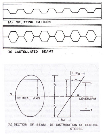
In addition to the above, expanded or castellated beams as shown in Fig. 13.2.B are used. The castellated beams are light beams and light beams and these are economically used for the light construction. The castellated beams are made by splitting the web of rolled steel I-sections in a predetermined pattern as shown in Fig. 13.2.A. The splitted portions are rejoined in such a manner as to produce a regular pattern of opening in the web.
13.3 BENDING STRESS
The bending stress is also termed as flexural stress. When the beams are loaded, they bend and bending stresses are setup at all the sections. The established theory of bending is expressed in the following formula:
![]()
Where, M = Bending moment
I = Moment of inertia
= Bending stress at any point
y = Distance from the neutral axis to the point under consideration
R = Radius of curvature of the beam
The above equation holds good when the plane of bending coincides with the plane of symmetry of the beam section. The bending of beam occurs in the principal plane of the beam section. The simple bending of beam occurs, i.e., the bending is produced by the application of pure couples at the ends of the beam. In such bending the deflection of beam does not occur due to shear. In the above equation, it is assumed that the vertical sections of the beam plane before bending remain plane after bending. Then stress in any given fibre is proportional to its strain, i.e., Hooke’s law holds good. For the material of beam, the value of E is same for the complete beam.
When the load is acting downward in a simply supported beam, then the distribution of bending stress for any section of beam is as shown in Fig. 13.3. The bending stress varies linearly. The bending stress is zero at the neutral axis. When the load is acting downward, the bending stress is compressive above the neutral axis of section and tensile below it and these are denoted by σbc.cal and σbt.cal respectively. The bending stress is maximum at the extreme fibre.
![]()
Where, Z is the section modulus (Z=I/ymax), ymax is the distance from the neutral axis to the extreme fibre and σb.max is the maximum bending stress.
The maximum bending stress in the beam section (if compressive) should be less than the allowable bending compressive stress and (if tensile); should be less than the allowable bending tensile stress. When the section of beam is symmetrical about the neutral axis then the value of ymax is equal to half the depth of section and the maximum bending stress in compression and in the tension at the extreme fibres are equal. When the beam section is not symmetrical about the neutral axis, then there are two distance y1 and y2 to the two extreme fibres from the nutral axis. The bending stresses at the extreme top and bottom are not equal. Then, the values of Z1=(I/y1) and Z2=(I/y2) both should be calculated and compared with the section modulus, Z of the beam section provided.
The total compressive force ‘C’ above the neutral axis is equal to the tensile force ’T’, for the beam in equilibrium. These two forces act in opposite directions and form a couple. This couple resists the bending moment and this moment is known as moment of resistance ‘Mr’. the moment of resistance of a beam section is the moment of the couple which is set up at the section by the longitudinal forces C and T created in the beam due to bending.
Mr=(C x Lever arm)=(T x Lever arm)
For the beam in equilibrium, the moment of resistance ‘Mr’ would be equal to the maximum bending moment ‘M’ at any section (Mr=M).
13.4. ALLOWABLE STRESS IN BENDING
The allowable bending stress, σbc in the design of rolled steel beam section considerably depends on the geometrical properties of the section and the lateral support. In case of flange width/flange thickness (½bf/tf) and the depth of section/thickness of web (h/tw) ratios not adequate, the elements of beam section will tend to buckle at low compressive stresses (which will be due to bending combined with axial loads). If the compression flange is not laterally supported (i.e., supports at intervals or uniformly) along the compression zone, it will either buckle in plane or cut-of plane coupled with twisting.
The rolled sections are produced with adequate (½bf/tf) and (h/tw) ratios such that the buckling of flange or web does not occur. The designers may provide supports at intervals or uniformly along he compression flange such that its buckling is avoided. The calculated bending compressive stress σbc.cal and bending tensile stress σbt.cal in the extreme fibres should not exceed the maximum permissible bending stress in compression (σbc) or in tension σbt as below.
σbc or σbt = 0.66 fy
The structural steel used in general construction may have yield stress as 220, 230, 240, 250, 260, 280, 300, 320, 340, 360, 380, 400, 420, 450, 480, 510 or 540 N/mm2 (M Pa). The structural steels having these values of yield stress are also used in flexural members. The maximum permissible bending compressive stress in beams and channels with equal flanges have been given separately in IS:800-1984. For an I-beam or channel with equal flanges bending about the axis of maximum strength (xx-axis), the maximum bending compressive stress on the extreme fibre, calculated on the effective section shall not exceed the values of maximum permissible bending compressive stress, σbc.
The safe compressive stress for a given grade of steel depends on a number of parameters as given below.
Let D=Overall depth of the beam
d1=Clear distance between the flanges
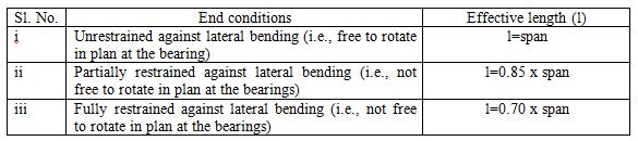
l=Effective length of the compression flange (Table 13.1)
ry=Radius of gyration of the section about its axis of minimum strength (yy-axis)
T=Mean thickness of the compression flange
t=Web thickness.
For the rolled steel sections, the mean thickness is that which one is given in ISI Handbook No.1. In the case of compound girders, with curtailed flanges, D shall be taken as the overall depth of the girder at the point of maximum bending moment and T shall be taken as the effective thickness of the compression flange and shall be calculated as
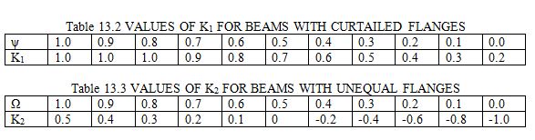
T = K1 x mean thickness of the horizontal portion of the compression flange at the point of maximum bending moment where K1 = a co-efficient given in Table 13.2
Table 13.1 EFFECTIVE LENGTH OF COMPRESSION FLANGE (l).
Restraint against torson can be provided by
i) Web or flange cleats, or
ii) Bearing stiffeners acting in conjection with the bearing of the beam, or
iii) Lateral end frames or other external supports to the ends of the compression flanges, or
iv) Their being built into wall.
Where the ends of the beams are not restrained against torsion or where the load is applied to the compression flange and both the load and the flange are free to move laterally, the above values of the effective length shall be increased by 20 percent.
The end constraint element shall be capable of safely resisting, in addition to wind and other applied external forces a horizontal force acting at the bearing in a direction normal to the compression flange of the beam at the level of the centroid of the flange and having a value to not less than 2.5 per cent of the maximum force occurring in the flange.
For cantilever beams of projecting length L, the effective length l to be used shall be taken as follows:
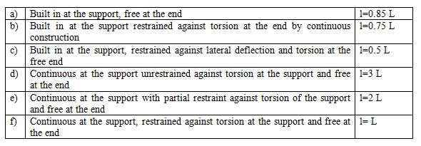
If there is a degree of fixity at the end, the effective length shall be multiplied by 0.5/0.85 in (b) and (c) above, and by 0.75/0.85 in (d), (e) and (f) above.
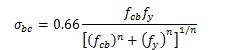
13.5 MAXIMUM PERMISSIBLE BENDING COMPRESSIVE STRESS IN BEAMS AND PLATE GIRDERS
For beams and plate girders bent about the x-x axis the maximum bending compressive stress on the extreme fibre, calculated on the effective section shall not exceed the maximum permissible bending compressive stress σbc calculated from the following formula.
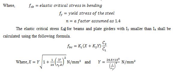
K1= a coefficient to allow for reduction in thickness or breadth of flanges between points of effective lateral resistant and depends on ψ1 the ratio of the total area of both flanges at the point of least bending moment to the corresponding area at the point of greatest bending moment between such points of resistant. Values of K1 for different values of ψ are given in the Table 13.2.
K2= a coefficient to allow for the inequality of flanges, and depends on ω, the ratio of the moment of inertia of the compression flange alone to that of the sum of the moments of inertia of the flanges, each calculated about its own axis parallel to the y-y axis of the girder, at the point of maximum bending moment. Values of K2 for different values of ω are given in the Table 13.3.
C1,C2=respectively the lesser and the greater distances from the section neutral axis to the extreme fibres.
Ix=moment of inertia of the whole section about the axis normal to the plane of bending (x-x axis) and
Iy= moment of inertia of the whole section about the axis lying in the plane of bending (y-y axis)
Values of X and Y for appropriate values of D/T and l/ry can be taken from standard text books on design of steel structures. Values of ![]() shall be increased by 20 per cent when
shall be increased by 20 per cent when ![]() and
and ![]() . The maximum permissible bending stress in tension σbt or in compression σbc in beams bent about the axis of minimum strength shall not exceed 0.66fy where fy is the yield stress of steel.
. The maximum permissible bending stress in tension σbt or in compression σbc in beams bent about the axis of minimum strength shall not exceed 0.66fy where fy is the yield stress of steel.
Last modified: Saturday, 5 October 2013, 8:17 AM