Site pages
Current course
Participants
General
MODULE 1. Electro motive force, reluctance, laws o...
MODULE 2. Hysteresis and eddy current losses
MODULE 3. Transformer: principle of working, const...
MODULE 4. EMF equation, phase diagram on load, lea...
MODULE 5. Power and energy efficiency, open circui...
MODULE 6. Operation and performance of DC machine ...
MODULE 7. EMF and torque equations, armature react...
MODULE 8. DC motor characteristics, starting of sh...
MODULE 9. Polyphase systems, generation - three ph...
MODULE 10. Polyphase induction motor: construction...
MODULE 11. Phase diagram, effect of rotor resistan...
MODULE 12. Single phase induction motor: double fi...
MODULE 13. Disadvantage of low power factor and po...
MODULE 14. Various methods of single and three pha...
LESSON 2. Determination of ampere-turns for series and parallel magnetic circuits
intro
Example 1
N turns of wire are wound around a toroidal core of a ferromagnetic material with permeability
µ. Determine Bf, in the ferromagnetic core; Hf in the core; and Hg in the air gap.
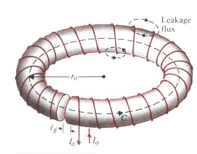
Fig. 1.3 Magnetic circuit
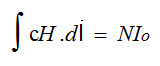
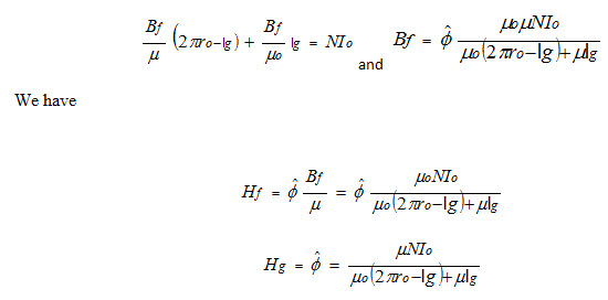
Applying Ampere’s circuital law
If flux leakage is neglected, the same total flux will flow in both the ferromagnetic core and in the air gap. If the fringing effect of the flux in the air gap is also neglected, the magnetic flux density (B) in both the core and the air gap will also be the same.
However, because of the different permeabilities, the magnetic field intensities in both parts will be different. We have
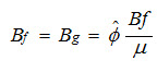
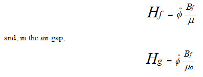
where the f and g denote ferromagnetic and gap, respectively. In the ferromagnetic core,
Ampere’s law
If the radius of the cross section of the core is much smaller than the mean radius of the toroid, the magnetic flux density B in the core is approximately constant, and the magnetic flux in the circuit is
Φ ≅ BS
where S is the cross-sectional area of the core.
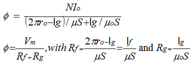
Both Rf and Rg are called reluctance.
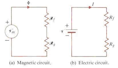
Fig. 1.4 Equivalent magnetic and electric circuit of the example1
Similar to Kirchhoff’s voltage law, we may write, for any closed path in a magnetic circuit,
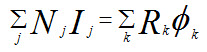
Around a closed path in a magnetic circuit the algebraic sum of ampere-turns is equal to the algebraic sum of the products of the reluctances and fluxes.
Kirchhoff’s current law for a junction is consequence of ∇ ⋅ J = 0 . Similarly ∇⋅ B = 0 leads to
∫ s B ⋅ d s = 0
Thus we have
∑ Φ j = 0,
Which states that the algebraic sum of all the magnetic fluxes flowing out of a junction in a magnetic circuit is zero.
Example 2 Solve the magnetic circuit in Fig. 1.5 (a)
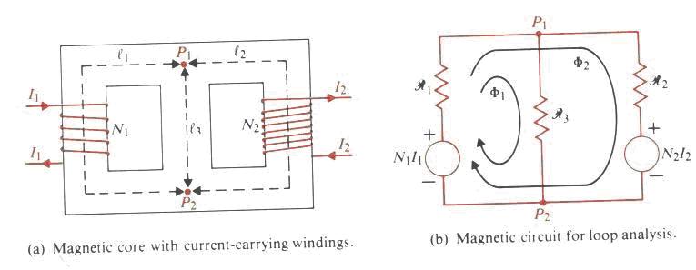
Solution
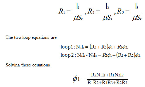
The reluctances are:
This is analogous to the electric circuits methods such as voltages around the loop and adding parallel and series resistances, etc.
It is to be noticed with great interest that, most of the electromechanical energy devices cores have a small gap, as in transformers, motors and generators. One of the reasons for a narrow gap is that as the air gap of a coil is increased, the linear inductance region of the coil will also increase, and the coil will not saturate for the same excitation current; which would cause saturation if the air gap was not included.
Magnetic circuit with air gap
Air gap requires much more mmf than the core
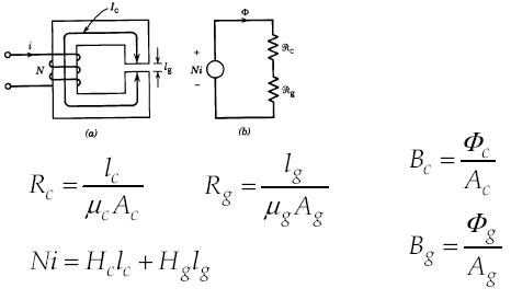
Below is another example on magnetic parallel circuit with an air gap.
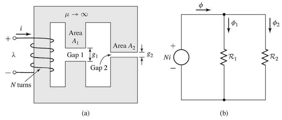
Fig. 1.6 Magnetic parallel circuit with an air gap
If we assume that there is no fringing then Ac = Ag (16)
But with an air-gap in a magnetic core, the flux fringes out into neighboring air paths as shown in Figure 1.6, these being of reluctance comparable to that of the gap. The result is non-uniform flux density in the air-gap (decreasing outward), enlargement of the effective air-gap area and a decrease in the average gap flux density. The fringing effect also disturbs the core flux pattern to some depth near the gap.
The effect of fringing increases with the air-gap length. Corrections for fringing in short gaps (as used in machines) are empirically made by adding one gap length to each of the two dimensions making up its area. For the core given in Figure 1.6, the air-gap reluctance, given by
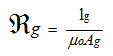
(17)
Should be calculated using an Ag which is greater than Ac.
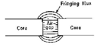
Fig. 1.7 Flux fringing at air gap.
It can be shown theoretically that the magnetic flux leaves and enters the surface of an infinitely permeable material, in a direction normal to the surface. This will be nearly so in ferromagnetic materials which have high permeability. In electrical machines a small amount of the tangential flux component present at iron surfaces will be neglected.
Adapted from EE360 course on Electric Energy Engineering, KFUPM Open Courseware