Site pages
Current course
Participants
General
MODULE 1. Electro motive force, reluctance, laws o...
MODULE 2. Hysteresis and eddy current losses
MODULE 3. Transformer: principle of working, const...
MODULE 4. EMF equation, phase diagram on load, lea...
MODULE 5. Power and energy efficiency, open circui...
MODULE 6. Operation and performance of DC machine ...
MODULE 7. EMF and torque equations, armature react...
MODULE 8. DC motor characteristics, starting of sh...
MODULE 9. Polyphase systems, generation - three ph...
MODULE 10. Polyphase induction motor: construction...
MODULE 11. Phase diagram, effect of rotor resistan...
MODULE 12. Single phase induction motor: double fi...
MODULE 13. Disadvantage of low power factor and po...
MODULE 14. Various methods of single and three pha...
LESSON 10. Power and energy efficiency, open circuit and short circuit tests, principles
Open-circuit Test
Figure 5.1 shows a transformer having the low side connected to an alternating source of supply and the high side open-circuited. Either an auto-transformer or a drop wire is shown as a means of varying the voltage supplied to the low side of the transformer. A voltmeter, an ammeter and a wattmeter are connected in the primary circuit. The voltmeter reads the voltage across the primary terminals, the ammeter reads the no-load current, and the wattmeter reads the power taken by the transformer under these conditions.
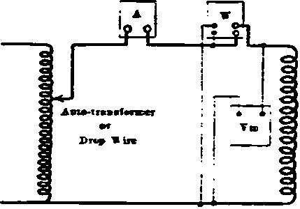
5.1 Connections for open-circuit test
This power goes to supply the primary I2R loss and the core loss of the transformer. As the exciting current is very small, the primary I2R loss due to it may be neglected. Therefore, the wattmeter reads the transformer core loss. If the primary voltage be varied and the core loss be determined for different values of voltage, a curve is obtained showing the relation of core loss to voltage. At no load the flux is practically proportional to the terminal voltage, as the primary impedance drop due to the no-load current is negligible. The eddy-current loss varies as the square of the voltage and the hysteresis loss as the 1.6 power of the voltage. The core loss will increase, therefore, nearly as the square of the voltage, as shown below (a).
Transformers are usually so designed that the most economical use of materials is obtained. Therefore, the core is operated at as high a flux density as the allowable core loss will permit. Figure 5.2 (a) shows that a slight increase of voltage, above rated voltage, produces a very large percentage increase in core loss. As transformers are rated by their maximum safe operating temperatures, this increased core loss may cause overheating of the transformer. Therefore, the effect of operating transformers at over-voltage is to produce a large increase in temperature.
If the magnetizing current be plotted as abscissa, and the voltage as ordinates, a saturation curve similar to that of figure 5.2 (b) is obtained. The point marked "rated voltage" is the point on the saturation curve at which transformers are generally operated, and is well beyond the knee of the curve. Outside the question of increased core loss, the usual transformer cannot be operated at a voltage very much in excess of its rated voltage, for the exciting current increases very rapidly with small increase in voltage, as indicated in figure 5.2 (b). The flux density in the core is determined primarily by the permissible core loss. Open-hearth annealed sheet steel, such as is used in dynamos, can be used for transformer cores. For a given flux density and frequency, however, silicon steel has much less core loss pen* unit volume than open-hearth steel, the effect of the silicon being to increase the electrical resistance, and hence reduce the eddy-current loss. Because of its small core loss, silicon steel may be operated safely at very high flux densities. The greater cost of silicon steel is more than offset by the saving in iron and in copper, and in the general reduction of the transformer dimensions.
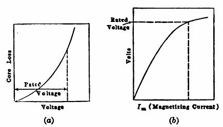
Fig. 5.2. Characteristics; (a) Relation of core loss to voltage in a transformer (b) Relation of magnetising current to voltage in a transformer.
To obtain the true value of the exciting current; the current measured by the ammeter, should be resolved into two components, one of which lies along the voltage –E1 or V and is shown as Ic in the figure 5.3 (-E1 and V are practically equal at no load). This current Ic = IO cos q is the energy component of the current and supplies the core losses. The quadrature component Im = IO sin q is the true magnetizing current.
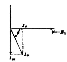
Fig. 5.3 Phasor diagram
Short circuit test
Figure 5.4 shows the transformer short-circuited on the secondary side.
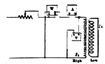
Fig. 5.4 Short circuit test
In a transformer, the impedance drop seldom exceeds 5 per cent of the rated voltage. If the 2,200 volt side of a transformer in figure 5.4 be used as the primary, the voltage necessary to send rated current through the windings on short-circuit is about 5 per cent of 2,200, or 110 volts, which is a standard voltage for instrument coils. If the secondary of the transformer were rated at 220 volts, the voltage at short-circuit would be only 11 volts and the current would also be high. At this low voltage, high precision could not be obtained with ordinary instruments. When a primary current I1 flows, the secondary current I2 is equal to I1 (N1/ N2). Therefore, no need of using an ammeter for measuring I2. The power delivered to the transformer, goes to supply three losses; the primary copper loss, I12R1, the secondary copper loss, I22R2, and the core loss at short-circuit. The core loss is negligible, as 5 per cent, primary voltage means only about 2.5 per cent of the rated value of flux, since half the impressed voltage on short-circuit is consumed in the primary impedance drop. The core loss at 2 or 3 per cent, of the rated flux is so small as to be negligible, for the core loss varies nearly as the square of the flux. Therefore, the power at short circuit
![]()
where R01 and R02 are the transformer equivalent resistances referred to the primary and secondary, respectively. The value of equivalent resistance as found in this manner may be checked with the value determined by measuring the resistance of each winding with direct current. The ratio of effective to ohmic resistance is only a few per cent, greater than unity in most transformers. Figure 5.3 shows the equivalent circuit vector diagram for the short-circuit test. This diagram is merely same as that of open circuit test, except that V2 now equals zero and all quantities are now referred to the primary side. It will be recognized that the entire voltage V1 is consumed in the impedance drops of the two windings. From this it is obvious that if Z01 be the equivalent impedance of the transformer, referred to the primary side,
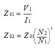
Knowing the equivalent impedance and equivalent resistance, the equivalent reactance is readily found as ![]() for either primary or secondary side. In making the short-circuit and the open-circuit tests, the question of instrument losses should be investigated and correction made if this be found necessary. As the losses in a transformer are very small, the power taken by the instruments may be a considerable percentage of the power being measured.
for either primary or secondary side. In making the short-circuit and the open-circuit tests, the question of instrument losses should be investigated and correction made if this be found necessary. As the losses in a transformer are very small, the power taken by the instruments may be a considerable percentage of the power being measured.
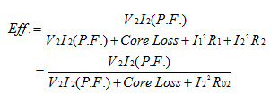
Regulation and Efficiency
The data obtained from the short-circuit and open-circuit tests are sufficient to compute the regulation and the efficiency of the transformer at any load. As the equivalent resistance and reactance referred to either side are known, it is merely necessary to determine the regulation. The procedure will be demonstrated by an example which follows. It has been pointed out that with constant voltage, the mutual flux of the transformer is practically constant from no load to full load. It usually does not vary more than from 1 to 3 per cent. Therefore, the core loss is practically constant at all loads and may be determined by the open-circuit test. For most purposes, it is necessary merely to measure the loss at the rated voltage of the transformer. The only other losses are the primary and secondary copper losses. These can be calculated readily, knowing the resistances of primary and secondary, or they may be computed from the equivalent resistance determined at short-circuit. The efficiency of the transformer may then be computed, since the losses are known. That is, the efficiency