Site pages
Current course
Participants
General
MODULE 1. Electro motive force, reluctance, laws o...
MODULE 2. Hysteresis and eddy current losses
MODULE 3. Transformer: principle of working, const...
MODULE 4. EMF equation, phase diagram on load, lea...
MODULE 5. Power and energy efficiency, open circui...
MODULE 6. Operation and performance of DC machine ...
MODULE 7. EMF and torque equations, armature react...
MODULE 8. DC motor characteristics, starting of sh...
MODULE 9. Polyphase systems, generation - three ph...
MODULE 10. Polyphase induction motor: construction...
MODULE 11. Phase diagram, effect of rotor resistan...
MODULE 12. Single phase induction motor: double fi...
MODULE 13. Disadvantage of low power factor and po...
MODULE 14. Various methods of single and three pha...
LESSON 23. Polyphase systems – delta in generation - three phase load connections
Delta connection
The three coils of Fig. 9.5 can be connected as shown in Fig. 9.10 (a), the diagram being simplified in Fig. 9.10 (b). The end of each coil, which was connected to the neutral in star (Y) earlier, is now connected to the outer end of the next coil, as shown in Fig. 9.10 (a). As points o and a are now connected directly together, the o's are now superfluous and are dropped. Fig. 9.11 (a) shows vectorially the three voltages Eab, Ebc and Eca, acting from a to b, b to c, and c to a, respectively. At first sight Fig. 9.10 looks like a short circuit, the three coils, each containing a source of voltage, being short circuited on themselves. The actual conditions existing in this closed circuit may be demonstrated by the use of the subscript notation. Assume that the coil bc is broken at c', Fig. 9.12 (a). The voltage Ebc = Eba + Eac. The vector sum of these two voltages, shown in Fig. 9.12 (b), lies along voltage Ebc’, and is equal to it. Therefore, the voltage Ecc' = 0 and points c and c' can be connected without any resulting flow of current. This is the same condition which exists when two direct current generators having equal voltages are connected in parallel. No current flows between the two if the proper polarity is observed.
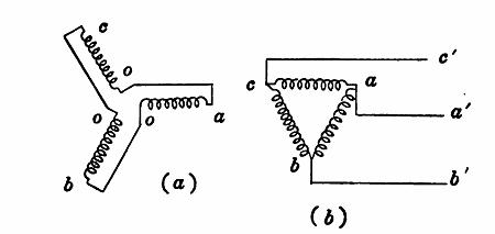
Fig. 9. 10 Delta connection of alternator coils.
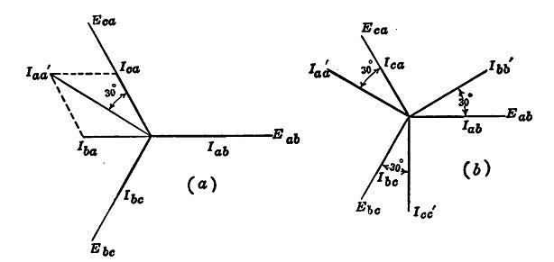
Fig. 9.11 Relation of coil voltages and currents in a delta system at unity power factor.
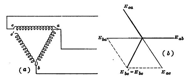
Fig. 9.12 Showing that Delta connection is not a short circuit
The coil currents of Fig. 9.10 are shown in Fig. 9.11 in phase with their respective voltages, balanced conditions being assumed. The line current
Iac’ = Iba + Ica
This addition is made vectorially in Fig. 9.11 (a), giving Iac’ 30° from Eca. It will be observed that Iac ' is Ö3 times the coil current. Line currents Ibb’ and Icc’ may be found in a similar manner, with the result shown in Fig. 9.11 (b). Therefore, in the delta system there is a phase difference of 30° between the line currents and the line voltages at unity power factor, just as in the star (Y) system. It is obvious that the line voltage is equal to the coil voltage in a delta system. Moreover, the sum of the three voltages acting around the delta must be zero by Kirchhoff's second law.
In a balanced delta system, the line voltage is equal to the coil voltage, but the line current is \/3 times the coil current.
Figure 9.13 shows three lamp loads, each requiring 10 amp at 115 volts. They are first connected in star (Y) and then in delta. In order to supply the proper voltage in each case, there are 199 volts across lines in the Y system and 115 volts in the delta system. There are 10 amp. per line in the Y system and 17.3 amp per line in the delta system. The power supplied is the same in each system.
Power in Delta system The total power in a delta system is
P = 3 Ecoil Icoil cosθcoil
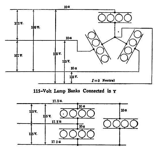
Fig. 9.13 Lamp loads in Y and in delta
This power is equal to that in the line, as there is no intervening loss. Also, the line current
Iline = √3 Icoil and Eline = Ecoil
Hence, substituting in the above equation P = √3 Eline Iline cosθload
This equation is the same as that developed for the star (Y) system. This should be so, for the relations in a three phase line are the same whether the power originates in a delta or in a Y connected generator. The power factor of the delta system is the same as that for a Y system.
P F. = P / √3 EI, where P is the total power of the system, and E and I are the line voltage and line current respectively.
The denominator, √3 EI, gives the volt amperes of the three phase system.