Site pages
Current course
Participants
General
MODULE 1. Electro motive force, reluctance, laws o...
MODULE 2. Hysteresis and eddy current losses
MODULE 3. Transformer: principle of working, const...
MODULE 4. EMF equation, phase diagram on load, lea...
MODULE 5. Power and energy efficiency, open circui...
MODULE 6. Operation and performance of DC machine ...
MODULE 7. EMF and torque equations, armature react...
MODULE 8. DC motor characteristics, starting of sh...
MODULE 9. Polyphase systems, generation - three ph...
MODULE 10. Polyphase induction motor: construction...
MODULE 11. Phase diagram, effect of rotor resistan...
MODULE 12. Single phase induction motor: double fi...
MODULE 13. Disadvantage of low power factor and po...
MODULE 14. Various methods of single and three pha...
LESSON 24. Polyphase induction motor – theory of operation
The induction motor is the most widely used type of alternating-current motor. This is due to its ruggedness and simplicity, the absence of a commutator, and the fact that its operating characteristics are suitable for constant speed work.

Fig. 10.1 Rotation of metal disc produced by rotating magnet.
The principle of the motor may be illustrated as follows: A metal disc in Fig. 10.1 (a), is free to turn upon a vertical axis. The disc may be of any conducting material, such as iron, copper, or aluminum. A magnet, free to rotate on the same axis as the disc, is placed above the disc and its ends are bent down so that its magnetic flux cuts through the disc. When this magnet is rotated, the magnetic lines cut the disc and induce currents in it, as shown in the figure Fig. 10.1. As these currents find themselves in a magnetic field, they tend to move across this field, just as the currents in the conductors of a direct-current motor tend to move across its magnetic field. By Lena's law, the direction of the force developed between these currents in the disc and the magnetic field producing them will be such that the disc tends to follow the magnet, as shown in the figure. In Fig. 10.1 (a), the north pole of the rotating magnet is shown as moving in a counter-clockwise direction. The conductor beneath the magnet also moves in a counter-clockwise direction, but more slowly than the magnet. Therefore, the relative motion between the magnet and the conductor is the same as if the magnet were stationary and the conductor moved in the clockwise direction. This relative motion of the magnet and the conductor is illustrated in (b), where the north pole is shown as being stationary and the conductor is moving from right to left. Applying Fleming's right-hand rule, the direction of the induced current is toward the observer. The lines of force about the conductor, due to its own current, are therefore counter-clockwise and the resultant field is found by combining the conductor field and the field produced by the magnet. The appearance of this resultant field is shown in (c). As the magnetic field is increased in intensity to the left of the conductor and reduced in intensity to the right of the conductor, there is a force developed which urges this conductor from left to right. That is, the conductor tends to follow the magnet. Actually, the magnet rotates in a counter-clockwise direction. Therefore, the disc rotates in the same direction but at a speed less than that of the magnet.
The disc can never attain the speed of the magnet, for were it to attain this speed, there would be no relative motion of the disc and the magnet and, therefore, no cutting of the disc by the magnetic flux. The disc current would then become zero and no torque would be developed, which would result in the disc speed becoming less than that of the magnet. So there must always exist a difference of speed between the two. This difference of speed is called the slip.
Alternating current Rotating Field
The rotating fields described in the previous paragraph were produced by rotating the magnetic poles mechanically. Rotating magnetic fields are, however, produced by sending polyphase currents through polyphase windings, such as alternator windings. Such rotating fields are produced entirely by electrical means, there being no mechanical rotation of the pole pieces themselves.
A cylinder may be used instead of the disc used earlier as shown in Fig. 10.2. Four poles are shown, the magnetic lines of which cut the cylinder. If the frame carrying these poles be revolved by mechanical means, the currents induced in the cylinder will cause the cylinder to rotate in the same direction as that of the rotating frame.
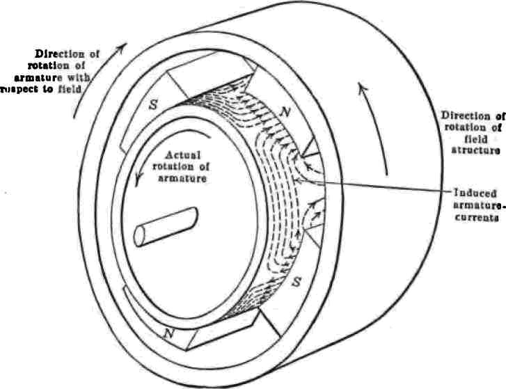
Fig. 10.2 Rotation of conducting cylinder due to induced currents.
The simplest type of rotating field is that produced by the gramme ring winding illustrated next. A gramme ring, wound for two-phase currents, has two separate windings, one for each phase. Each winding consists of two sections located diametrically opposite each other and each section occupies approximately one-fourth the winding space of the ring. The two windings are called the A-phase and the B-phase, respectively. Care must be taken to connect the two sections of each winding correctly as shown. Curves IA and IB show the variation with time of the currents in phases A and B, respectively. As these are two-phase currents, they differ in time-phase by 90° or one-fourth of a cycle. At the instant marked (1) in Fig. 10.3, the current in phase A is zero and that in B is negative maximum. With the method of connecting the windings, and the direction of the currents as shown, two South poles are formed on the upper ends of the B-windings and two N-poles on the lower ends.
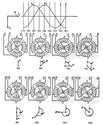
Fig. 10.3 Rotating field produced by 2-phase currents in gramme-ring winding.
These four poles combine into two poles, a single S-pole and a single N-pole, each of these last being twice the magnitude of the individual poles which combined to form them. The resultant field is vertical and is directed upwards, as indicated by the arrow F beneath diagram Fig. 10.3 (1). In Fig. 10.3 (2) the current in B is still negative, but of lesser magnitude than in Fig. 10.3 (1). The current in A has increased positively until its magnitude is equal to that of B. Two S-poles and two N-poles again combine to form a single S-pole and a single N-pole, each of double the magnitude of the individual poles forming them. The direction of the resulting field is 45° clockwise from its position in Fig. 10.3 (1). It is to be noted that while the two currents are passing through 45 electrical time-degrees, the resulting field in the gramme ring advances 45 space-degrees. Diagrams Fig. 10.3 (3), (4), (5), (6), (7), and (8) show at different instants the positions of the gramme ring field resulting from the combined magnetic effects of phases A and B. The diagram for Fig. 10.3 (9) would be identical with that for Fig. 10.3 (1). The rotating magnetic field has passed through 360 space-degrees while the two-phase currents have gone through 360 electrical time-degrees or one cycle. This constitutes a two pole rotating field and its speed in revolutions per second is the same as the frequency, or the cycles per second, of the currents. For example, if the currents had a frequency of 60 cycles per second, the field would make 60 revolutions per second, or 3,600 r.p.m.
The commercial polyphase induction motor consists of a fixed member called the stator, carrying a polyphase drum winding (wrapped inside the stator from one side to another like on a drum), and a rotating member called the armature or rotor. As the stator usually receives the power from the line it is called the primary, and as induced currents flow in the rotor, it is called the secondary, just as in the transformer. The figure Fig. 10.4 shows four successive positions of the rotating field, for corresponding values of the polyphase currents in the stator of a three-phase induction motor.
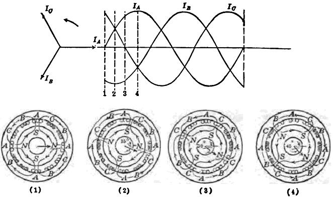
Fig. 10.4 Rotating field produced by 3-phase currents in a 4-pole, induction-motor winding.
In Fig. 10.4 (1) the current IA is zero, so that IB and Ic are opposite and equal. The position of the field is shown at this instant. In Fig. 10.4 (2) the currents IA and Ic are but half their maximum positive values and their positions on the stator are such that their phase belts are on each side of B-belt in which the current is a maximum. Therefore, the field is symmetrical at this position.
It will be noted also that the time-angle between successive values of current in 1-2-3 is 30 electrical-degrees, whereas the field advances but 15 space-degrees between Fig. 10.4 (1) and (2) and also between Fig. 10.4 (2) and (3). Between positions Fig. 10.4 (1) and (4) the currents have advanced 90 electrical time-degrees, but the rotating field has advanced only 45 space-degrees. That is, the advance of the rotating field in space-degrees is equal to one-half the advance of the currents in electrical time-degrees. Therefore, the speed of such a field in revolutions per second is equal to one-half the circuit frequency in cycles per second.
In general it may be stated that in order to produce a two-pole rotating field, the angular space-degrees between the phase belts of the winding must be the same as the electrical time-degrees between their respective currents. If the machine has p poles, the angular space-degrees between phase belts is 2/p times the electrical time degrees between their respective currents. For example, in a six-pole, three-phase machine, the successive phase belts start 40° from each other, that is, (2/6) × 120° or 40°.
Synchronous Speed.
It was just shown that the angular speed of an alternating current rotating field depends upon the frequency of the current and the number of poles for which the machine is wound. The relation between speed, frequency and poles is given by the following equation:
N = 120 f /p
where N is the speed of the rotating magnetic field in r.p.m, f the frequency in hertz and p the number of poles. This speed the rotating magnetic field,is called the synchronous speed of the motor. The common synchronous speeds for commercial motors running on a supply of 50 hz are as follows:
|
Poles |
RPM |
|
2 |
3000 |
|
4 |
1500 |
|
6 |
1000 |
|
8 |
750 |
|
12 |
500 |