
Site pages
Current course
Participants
General
MODULE 1. Electro motive force, reluctance, laws o...
MODULE 2. Hysteresis and eddy current losses
MODULE 3. Transformer: principle of working, const...
MODULE 4. EMF equation, phase diagram on load, lea...
MODULE 5. Power and energy efficiency, open circui...
MODULE 6. Operation and performance of DC machine ...
MODULE 7. EMF and torque equations, armature react...
MODULE 8. DC motor characteristics, starting of sh...
MODULE 9. Polyphase systems, generation - three ph...
MODULE 10. Polyphase induction motor: construction...
MODULE 11. Phase diagram, effect of rotor resistan...
MODULE 12. Single phase induction motor: double fi...
MODULE 13. Disadvantage of low power factor and po...
MODULE 14. Various methods of single and three pha...
LESSON 26. Polyphase motor - Phase diagram, torque equation, starting and speed control methods
Alternating-current Torque
In DC motors, we learnt that torque is proportional to the current and to the density of the magnetic field in which the current finds itself. This is true for alternating current motors also, provided the instantaneous values of current and flux are considered.
If the slip is small, the reactance of the rotor conductors is low because f2 = sf and X2' = 2πf2L2, where f is the stator frequency, X2' is the rotor reactance at slip s, and L2 is the rotor inductance. Because of the rotor reactance the rotor current lags the induced emf. of the rotor by an angle a. At low values of slip, this angle a is very small, since tan a= 2π fsL2/R2, where R2 is the rotor resistance.
The induced emf in any single conductor, l centimeters in length, in a field having a density of B gausses, the conductor moving at a velocity of v cm/s with respect to the field, is e = Blv10-8 volts, the flux, the conductor and the velocity being mutually perpendicular Therefore, when a conductor is cutting flux at a uniform velocity, the flux being sinusoidally or otherwise distributed in space, the emf in the conductor is zero when it is moving in a region where B, the flux density, is zero; the emf is a maximum when the conductor is moving in a region where B the flux density, is a maximum.
Alternating-current torque when current and flux are in space-phase. It may be said that e, the emf per conductor, is in phase with the flux. It further follows that
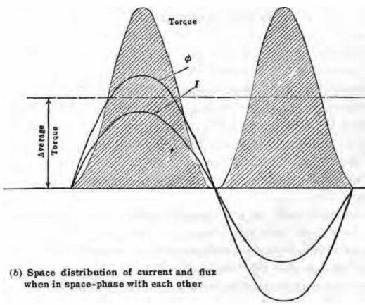
Fig. 11.1 Torque developed
the wave shape of the emf. in a single conductor is the same as the shape of the space-distribution curve of the flux. At small values of slip, the angle a, between the induced emf in each conductor and the current in the conductor, is small and therefore the current in each of the conductors, is practically in phase with its induced emf. As the induced emf is a maximum when the conductor is in the field of greatest flux density, the current will be a maximum at practically the same instant. The current is then in time-phase with the emf and hence in space-phase with the flux. Under these conditions the current in the particular conductor which is under the center of the pole, is a maximum, and that in the other conductors is less, decreasing sinusoidally as indicated.
The force acting on each conductor is proportional to its current and to the flux density of that part of the field in which the conductor finds itself. The torque curve (Fig. 11.1) is obtained by taking the product of the current and flux at each point at each point, multiplied by a constant. It will be noted that this torque curve is of double frequency, it is always positive and reaches zero twice every cycle.
As the value of the slip increases, the reactance of the rotor increases, the reactance being proportional to the rotor frequency and hence to the slip, and the angle a by which the current lags its induced emf increases, since tan a = 2π fsL2/R2. The current in any conductor will not reach its maximum value until a time-degrees after the induced emf has reached its maximum value.
Operating Characteristics of the Squirrel-cage Motor
The squirrel-cage motor, like the direct-current shunt motor, operates at substantially constant speed. As the rotor cannot reach the speed of the rotating magnetic field, it must at all times operate with a certain amount of slip. At no load the slip is very small. As load is applied to the rotor, more rotor current is required to develop the necessary torque in order to carry the increased load. Consequently, the rotating magnetic field must cut the rotor conductors at an increased rate, in order to produce the necessary increase of current. The slip of the rotor must accordingly increase, so that the rotor speed drops. The ratio of the slip to the total power delivered to the rotor is proportional to the I2R loss in the rotor. As the resistance of the squirrel cage is very low, the I2R loss is low and, therefore, the slip for ordinary loads is small. In large motors, 50 hp. or greater, the slip is of the order of 1 to 2 per cent, at full load. In the smaller sizes of motor, the slip may be as high as 8 to 10 per cent at full load.
Figure 11.2 shows the characteristic curves of a 10-hp. squirrel-cage motor. It will be noted that the torque, speed and efficiency curves are very similar to those of a shunt motor.
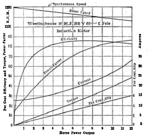
Fig. 11.2 Operating characteristics of a squirrel-cage induction motor.
|
Fig. 11.3 Increase of power factor with load |
The power factor increases with the load for the following reason: At no load the motor takes a current I0, in figure 11.3, which is mostly magnetizing current, although there is a small energy component necessary to supply the no-load losses. The power factor at no load is cos q0, the value of which may be as low as 0.10 to 0.15. The back emf of the motor remains nearly constant from no load to full load. Therefore, the flux must remain substantially constant, just as it does in the transformer, so that the magnetizing current changes but slightly from no load to full load. As load is applied to the motor, an energy current I1’ is required to carry the load. This current, when combined with I0, gives the total current I1 at this load, and the resulting power-factor is cos qi. As the load increases, an energy current I2’ is required. The total current then becomes I2 and the corresponding power-factor becomes cos q2. It will be observed that the power factor angle decreases and therefore the power factor increases as the load on the motor increases. The increased reactance drops in the stator and in the rotor with increase of load tend to oppose this increase of power-factor and when the load exceeds a certain value may even bring about a decrease of power-factor.
As the power-factor increases, a smaller increase of current is required for a given increase of load than would be necessary if the power factor were constant. Therefore, the current increases more slowly than the load as shown. At first the efficiency increases rapidly and reaches a maximum value for the same reason that it does in other electrical apparatus. At all loads there are certain fixed losses, such as core loss and friction. In addition there are the load losses (I2R) which increase nearly as the square of the load. Therefore, at light loads the efficiency is low because the fixed losses are large as compared with the input. As the load increases, the efficiency increases to a maximum, the fixed and variable losses being equal at this point. Beyond this point the I2R losses become relatively large, causing the efficiency to decrease.
One disadvantage of the squirrel-cage motor lies in the fact that it takes a very large current at low power-factor on starting, and in spite of this large current it develops little torque. When the motor is at standstill, the squirrel cage acts as the short-circuited secondary of a transformer, causing the motor to take an excessive current on starting, if full voltage is applied.
Figure 11.4 shows the variation of torque with slip for two different values of line voltage. For small values of slip up to and beyond full load, which is the ordinary range of operation, the torque is substantially proportional to the slip. At higher values of slip, however, the torque curve bends over and finally reaches a maximum. This maximum is called the break-dawn torque.
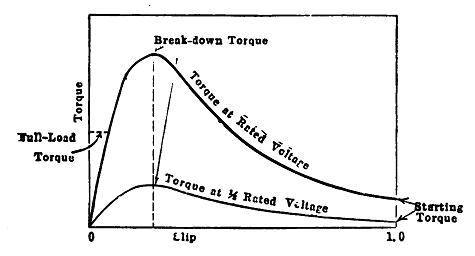
Fig. 11.4 Slip-torque curves for squirrel-cage motor.
It is also true that the torque of an induction motor for a given slip is proportional to the square of the line voltage. For this reason a 10 per cent drop in voltage (Fig. 11.4), may cause a 19 per cent reduction in the break-down and starting torques.
The stator impedance also reduces the break-down torque. A high stator impedance means a comparatively large impedance drop in the stator for a given current. This decreases the back emf, E, hence the air-gap flux becomes less, and therefore the value of the rotor current at any given slip is reduced. This results in a reduction of torque for each value of slip.
The effect of each of these various factors upon the break-down torque is shown in the following equation: The break-down torque
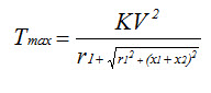
where K is constant, V is the terminal voltage, r1 is the stator resistance, x1 is the stator reactance, and x2 is the rotor reactance at standstill. As the squirrel-cage motor is ordinarily started at low voltage, it develops but little starting torque, because the flux is small.
Small induction motors are directly connected through simple 3 pole switches and the higher starting current is not minded much. Because the magnitude of current is relatively less. Howver for motors of more than 3 hp, the higher starting current should reduced to save the motor. As the squirrel cage motor at starting is equivalent to a short-circuited transformer, it is necessary to reduce the starting current in the larger sizes. One simple method as shown in figure 11.5 is to use a delta-connected motor. By means of a triple-pole, double-throw (T.P.D.T) switch the windings are first thrown in star across the line, thus applying only l/3 of the normal voltage to each coil. This makes the line current one-third the value if the motor were directly across the line. When the motor has attained sufficient speed, the switch is thrown over, connecting the motor in delta across the line.
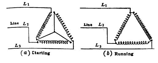
Fig. 11.5 Star delta method of starting an induction motor.