Site pages
Current course
Participants
General
MODULE 1. Electro motive force, reluctance, laws o...
MODULE 2. Hysteresis and eddy current losses
MODULE 3. Transformer: principle of working, const...
MODULE 4. EMF equation, phase diagram on load, lea...
MODULE 5. Power and energy efficiency, open circui...
MODULE 6. Operation and performance of DC machine ...
MODULE 7. EMF and torque equations, armature react...
MODULE 8. DC motor characteristics, starting of sh...
MODULE 9. Polyphase systems, generation - three ph...
MODULE 10. Polyphase induction motor: construction...
MODULE 11. Phase diagram, effect of rotor resistan...
MODULE 12. Single phase induction motor: double fi...
MODULE 13. Disadvantage of low power factor and po...
MODULE 14. Various methods of single and three pha...
LESSON 30. Disadvantage of low power factor and power factor improvement
Reactive Power
In any AC system, a purely resistive load, for example, electrical resistance heating, incandescent lighting , etc., the current and the voltage are in phase. Whereas, in the case of inductive loads, the current is out of phase with the voltage and it lags behind the voltage. Most of the equipment are inductive in nature such as inductive motors. In the case of a capacitive load the current and voltage are again out of phase but now the current leads the voltage. The most common capacitive loads are the capacitors installed for the correction of power factor of the load. Inductive loads require two forms of power - Working/Active power (measured in kW) to perform the actual work of creating heat, light, motion, etc., (consumed in the resistive portion of the load) and Reactive power (measured in kVAr) to sustain the electromagnetic field. The vector combination of these two power components (active and reactive) is termed as Apparent Power (measured in kVA), the value of which varies considerably for the same active power depending upon the reactive power drawn by the equipment. The ratio of the active power (kW) of the load to the apparent power (kVA) of the load is known as the power factor of the load.
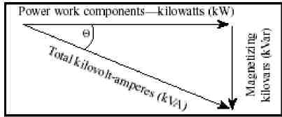
Fig. 13. 1. Apparent power
Power Factor = Active Power (kW) / Apparent Power (kVA)
Thus when the nature of the load is purely resistive the kVAr or the reactive component will be nil and thus the angle φ will be equal to 0 degrees and the power factor will be equal to unity. For a purely inductive load the power factor will be 0.0 lagging and for a purely capacitive load the power factor will be 0.0 leading.
Thus, it is evident from above that, more the power factor departs from unity, the more will be the apparent (kVA) demand for the same real (kW) load. The customers with a low power factor will pay more for their useful electrical power.
The disadvantages of a low power factor are :
1. The load draws greater current for the same value of the useful power.
A simple example showing the current required by a single phase electric motor is given below:
Supplied Voltage –240 Volts Single phase.
Motor input – 10 KW
Power Factor – 0.65
Current (I1) = Power (kW) /Volts (V) * PF = 10000/ 240*0.65 = 64.1 Amp.
If the power factor of the motor is increased to 0.9 the current drawn by the motor shall be –
Current (I2) = 10000/ 240*0.9 = 46.3 Amp.
Thus, as the power factor decreases the current required for the same value of active, or useful, power increases. So the sizes of the equipment, like the switchgear, cables, transformers, etc., will have to be increased to cater the higher current in the circuit adding cost. Further, the greater current causes increased power loss or I2R losses in the circuits. Also due to higher current, the conductor temperature rises and hence the life of the insulation is reduced.
2. With the increased current, the voltage drop increases, thereby the voltage at the supply point.
Example : Let us take an example of a cement industry with initial load condition of 5000 kVA at 60% power factor with a consumption of 19,20,000 units per month, supplied at 33 KV.
Assuming the Tariff as below:
Demand charges Rs. 144/kVA/month
Energy Charges Rs. 4.11 / Unit
PF surcharge for each 1% below 90% 1% of (Demand charges + Energy Charges)
A. Cost saving due to Power Factor improvement
(i) By improving the power factor, there will be a reduction in the kVA demand of the load.
Power Factor= cos φ = kW/ kVA
Cosφ1 = 0.6 = kW/kvA1 = kW/5000; KW=5000*0.6
Cosφ2 = 0.9 = kW/kVA2; KW=kVA2*0.9
Equating, 5000*0.6=kVA2*0.9; kVA2=(5000*0.6)/0.9 = 3333.33 kVA
Thus, in this case the kVA is dropped from 5000 kVA (at 60%) to 3333.33 kVA (at 90%):
Therefore reduction in energy bill due to reduction in maximum demand due to improved power factor from 0.6 to 0.9 shall be :
Rs. 144.00 * (5000-3333.33)= Rs. 240000.48 per month
(ii) In addition, by increasing the power factor from 60% to 90%,, there shall be no power factor penalty/surcharge on account of low power factor. Thus the savings due to avoidance of the PF surcharge per month would be as below:
Rs. ((5000-3333)*144*(90-60))*1/100= Rs.72014.14
(iii) Thus the total monthly reduction in bill due to P.F improvement from 0.6 to 0.9 would be:
Rs. 240000.48 + 72014.14 = Rs. 312014.88 per month.
Net reduction per annum = 312014.88*12 = 3744178.56 ~ Rs.37,44,179/-
Cost of investment for Power Factor improvement:
Size of capacitor required to improve the PF from 0.6 to 0.9
Reduction in reactive power
= kVA1* Sinφ1 – kVA2* Sinφ2 =5000*sin(53.1) – 3333.33*Sin(25.84)
=5000*0.8 - 3333.33*0.436 =4000-1453=2547 kVAr say 2550 kAVr
If we take the cost of capacitor bank per kVAr as Rs. 200/- , the cost of the capacitor bank = 2550*200 = Rs. 5,10,000/-
Cost of switching and associated equipment = Rs. 3,00,000/-and installation, etc.
Total cost = Rs. 8,10,000/-
Annual depreciation and interest@ 20% = Rs. 810000*0.2
= Rs. 1,62,000/-
Net Annual saving = 37,44,179 - 1,62,000 = Rs. 35,82,179/-
Net monthly saving = Rs. 2,98,515/-Therefore payback period = 2.7 months
Improving Power Factor :
Improving power factor by reducing the kVAr load requires the use of power factor equipment which operate at a leading power factor such as:
Synchronous motors which are either over-excited or under loaded with full excitation so they will supply kVAr to the electrical system.
Static capacitors which are electrical devices without moving parts that have the ability to provide magnetizing current to the load. Their efficiency is high since losses are less than one-half of 1 percent of their kVAC (or kVAR) rating.
The synchronous condenser is a synchronous motor without shaft extensions (so it cannot carry any mechanical load) which idles across the power system. Increasing its field excitation results in its furnishing magnetizing power (kVAr) to the system. Its principal advantage is the ease with which the amount of correction could be adjusted. These machines are automatically controlled and generate or consume reactive power depending on the system requirement. The synchronous converter is a machine with both slip rings and a commutator connected to the armature windings. This could supply direct current in much the same way as a conventional motor-generator set, but with some economy of size, weight, and material. Adjustment of the field excitation changes the amount of magnetizing power it could supply to the alternating current power lines. Both of these machines have been replaced principally by the use of static capacitors.
Static Capacitors:
Static capacitors are the cheapest and the simplest means for reactive power compensation . They are installed by power utilities in the transmission and distribution network and also at the consumers’ place on to different loads such as motors, transformers, incoming supply, etc. In present days automatic switching of the capacitors enables keeping a high power factor for heavily fluctuating loads as well.
Compensation or Power Factor Correction
Based on the reactive power requirement at their installations, the consumers have to provide for the necessary reactive compensation at their end to achieve the minimum power factor level prescribed by the utility. The most economical and reliable method of reactive compensation is the installation of power capacitors. Lagging power factor can be corrected by connecting capacitors in parallel with the system. The current in a capacitor produces a leading power factor. Current flows in the opposite direction to that of the inductive device. When the two circuits are combined, the effect of capacitance tends to cancel that of the inductance. Most customer loads (particularly motors, but many lighting circuits also) are inductive.
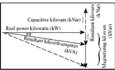
Fig. 13.2. resultant kVAr component after correction.
In figure 13.2, note the smaller resultant with the capacitors added, but real power (kW) does not change. A properly chosen capacitance value will neutralize the inductance and produce unity power factor.
Methods of correction
a. For motors of 50 hp and above, it is best to install power factor correction capacitors at the motor terminals since distribution circuit loading is reduced. When this is done, motor settings that are over current protection relays must be adjusted down accordingly.
b. In the second arrangement capacitor banks are connected at the bus for each motor control centre. This compromise to Method 1 will reduce installation costs.
c. In the least expensive method the capacitor banks are connected at the service entrance. However, the disadvantage is that higher feeder currents still flow from the service entrance to the end of line equipment.