Site pages
Current course
Participants
General
Module 1: Fundamentals of Reservoir and Farm Ponds
Module 2: Basic Design Aspect of Reservoir and Far...
Module 3: Seepage and Stability Analysis of Reserv...
Module 4: Construction of Reservoir and Farm Ponds
Module 5: Economic Analysis of Farm Pond and Reser...
Module 6: Miscellaneous Aspects on Reservoir and F...
Lesson 25 Construction
25.1 Introduction
After deciding the components and their dimensions, the next step begins is the construction of reservoir and/or farm pond. Further the site selection and location of the reservoir or farm pond in the selected site to be finished before the construction work begins. This lesson deals with the detail construction procedure.
25.2 Setting the Dam Site
This should be completed immediately prior to the start of construction to avoid unnecessary ground clearing and the loss of pegs and benchmarks. The dam centre line must be established with reference pegs, installed at each end of the centre line, a good distance from where construction will occur. If the original benchmark(s) is (are) not satisfactory another should be established on a permanent site within easy reference distance.
The centre line pegs should be installed at the ends of the embankment and at every change in ground level. For each change in ground level a mating peg (Fig.25.1) should be established by level or GPS on the opposite side of the valley, but still on the centre line.
At each peg on the centre line of the embankment, the distances of the toe pegs upstream and downstream are calculated and set out at right angles (Fig. 25.2). Unless it is a very small dam, it is advisable to make an extra allowance of 10 percent on the height of the embankment for future settlement.
If this is not done at this stage the process can become very tedious and time consuming, as pegs have to be offset from the toe peg or centre line at every construction level.

Fig. 25.1. Mating pegs. (Source: Stephen, 2010)
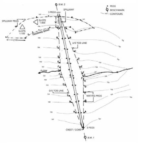
Fig. 25.2. Pegging layout. (Source: Stephen, 2010)
For every small dam (i.e. less than 5 m high) it is common to add a settlement allowance to the top of the embankment at the end of construction.
Pegs will be required to indicate the core and crest. If the core is central and has the same width as the crest, the pegs will serve a dual function. The toe peg offset distances from the centre line are calculated using the formula:
![]()
Where, S= slope, H= height of the embankment (m), including 10 percent allowance, and Cw= crest width (m)
On the spillway side, pegs are located where the spillway cut (if any) begins and ends and additional pegs are placed in an arc along the sides of the spillway channel (Fig.25.2). A 15 m interval between pegs is desirable and each should show the depth of the excavation required, note being made of the slope within the spillway itself (usually 1:400) needed to encourage flood water to flow away from the training bank and end of the embankment.
When all the pegs have been installed, and a full pegging layout drawn up, all the ramifications of the project can be discussed with the client and / or plant operator so that any risk of error and opportunity for misunderstanding are minimized and use of equipment and efficiency maximized.
25.3 Compaction Equipment and Techniques
The compaction of soil is essential to increase the shear strength of a material to achieve high levels of embankment stability. A high degree of compaction will increase soil density by packing together soil particles with the expulsion of air voids. Comparing the shear strength with the moisture content for a given degree of compaction, it is found that the greatest shear strength is generally attained at moisture contents lower than saturation.
If the soil is too wet, the material becomes too soft and the shear stresses imposed on the soil during compaction are greater than the soils shear strength, so that compaction energy is dissipated largely in shearing without any appreciable increase in density.
If the soil is too dry, a material compacted in this condition will have a higher percentage of air spaces than a comparable soil compacted wet. It will take up moisture more easily and become more nearly saturated with consequent loss of strength and impermeability. A damp soil, properly layered and compacted with a minimum of air voids also reduces the tendency for settlement under steady and repeated loading.
In dam construction, following correct compaction techniques is probably as important as choosing the correct materials. Where laboratory analysis is not available the following guidelines should be adhered to:
The soil to be compacted must be damp but not too wet and it must be layered along the full length of the embankment in depths appropriate to the equipment used. Farm machinery (e.g. tractor tyres filled with water following a staggered track or small rollers) and hand methods are usually only sufficient to successfully compact layers 75-100 mm deep. Heavier plant such as sheep foot rollers (ideal for clayey soils), vibratory and smooth wheeled rollers (ideally for sandy soils) can work with layers up to 200 mm thick and obviously are preferable where large quantities and widths require compaction.
Where soil moisture content is low, borrow pit irrigation always results in a more uniform distribution of water in the soil to be compacted. It is also more economical than adding water to the construction surface and often assists working of the soil by the excavators. Time is saved on the embankment to avoid watering the surface between layers. Judicious planning with ripping and ploughing of the borrow area before irrigation and allowing the water to soak in over one or more days (depending on climate, soil type, and quantity of water applied) before excavation will assist the development of uniform moisture contents in the earth fill materials.
Always adopt compaction techniques that will reduce the gross depth of any layer by at least 25 percent.
Rollers
Ø Sheeps foot Rollers can compact layers of soil up to 200 mm deep gross (i.e. about 150 mm after compaction) and satisfactory densities can normally be obtained with 6-12 passes at a roller speed of 3-6 km/h when the soil moisture content is optimum. It is important to keep these rollers clean as soil collecting between the feet will reduce compacting ability. Sheep foot rollers are more effective than other rollers in compacting drier clay (but will require more passes) and will churn and blend the soil which is useful in distributing water throughout the construction surface when borrow pit irrigation is not possible.
Ø Vibrating Rollers are more suited to the compaction of sandy soils and where resulting very high densities are required. In dam construction their usefulness is usually limited to small scale work such as narrow cut off compaction, trench work and similar.
Ø Rammers and Plates are used under specialized work such as trenches, behind concrete and around pipe work.
Ø Smooth Wheeled Rollers are more efficient at reducing air-spaces and continue the compaction of lower layers of the embankment through new layers to a greater extent than comparable sheeps foot rollers. On similar layer depths and at the same speed, a smooth wheeled roller would probably require slightly fewer passes to obtain similar soil densities when compared with sheeps foot rollers. However, the latter often prove more appropriate in use for dam construction as their lighter weight and versatility allow them to be pulled by farm machinery on a variety of surfaces. On clay soils, smooth wheeled rollers can form seepage paths between the layers of soils laid on the embankment. If a sheep foot roller is not available to compact such soils, gross depth of clay layers should be reduced and final surfaces roughened (by harrowing or similar) to permit a good bonding between compacted layers.
25.4 Site Clearing and Preparation
Base of the Dam
All tree roots, grass roots, and topsoil must be removed. Once the trees have been removed the dam scoop or scraper can be used to remove about 100 mm of top soil which can then be left in a position from where it can be later retrieved to dress the completed embankment or other disturbed areas.
Borrow Areas
Borrow areas should have been demarcated according to its usefulness.
Sometime previous to the start of construction, if possible, analysis of soil samples being undertaken by a local soils laboratory. For smaller dams, a visual or rough physical assessment may suffice.
The high percentage organic material at top layer must be removed and put to one side for future use. Although borrow areas within the proposed reservoir are desirable, care must be used to make sure that permeable layers are not exposed by the removal of impermeable soil above, as this process, if conducted close to the embankment, could lead to seepage problems later. Also no excavation should occur nearer than 10 m from the toe of the embankment.
Excavated soil (from the borrow pit) must be frequently monitored to check that its quality and moisture content has not changed and that it is still suitable for emplacement in the embankment. The core and cutoff trench require good quality clay. Compaction of the core and cutoff trench is important and the amount of compaction required in all sections will vary from site to site according to the soil quality. Generally drier and lower clay percentage soil requires more compaction and vice versa. Soils of around 20-30 percent clay are ideal as core material and those of lower percentage clay for the upstream shoulder.
25.5 Settlement
As the dam settles the crest should fall close to horizontal. It is important to check this by survey every few months in the first years of operation to ensure over or uneven settlement does not occur. If this does occur, remedial measures (filling by topsoil and grass is usually sufficient) will be required to restore the crest to its design level.
If proper and/or coarser soils are to be used, some increase in the settlement allowance considered at the setting out stage may be necessary. In most cases this increase should not be more than 15 percent overall.
25.6 Spillway
Natural spillways are generally best for all earth dams and farm ponds but often some degree of cut is required to obtain the necessary design slopes. In all cases the movement of machinery over the spillway area should be minimized to avoid over compaction of the existing soil, establishing track ways (which could lead to erosion later), and destroying any existing grass cover. Where a cut is required, it should be kept to a minimum and, unless unavoidable should not completely remove the topsoil. Depending on soil condition, sometimes additional depth is required to cut because of good quality topsoil and grass cover that will have to be placed once the desired profile has been attained. Any large volume spillway cut should be done at a time when the excavated material(if suitable) can be included with the material being moved to construct the main embankment or reserved to fill in borrow pits. Smaller volumes of cut material can usually be included in the training bank.
25.7 Embankment Constructing
The core/cutoff trench
As this is the most important part of any embankment, great care is necessary in the excavation, fill and use of material. Width and depth should have been determined at the design stage. Width (2 m minimum) will often depend on the equipment used in the excavation and also on the size of the dam.
The minimum depth necessary will depend on site conditions but in all excavations the cutoff trench must be taken down to good quality impermeable material such as clay or solid rock or to a minimum of three quarters of the dam’s crest height. If rock is located and is generally good, it is permissible to fill any cracks or fissures with compacted clay or mortar, provided they can be fully cleaned and traced to ensure seepage paths will not develop later. If an impermeable layer of sufficient thickness has not been reached and the trench depth is to the required 0.75H, the cutoff trench excavation can stop only if the material encountered is not of a coarse of gravelly nature (as often occurs in streambeds). If permeable material is found it is vital that the cutoff is taken through it to a depth sufficient to find more impermeable material.
Before backfilling, the excavation should be checked to ensure that the conditions above have been complied with. Short cuts taken at this stage can prove costly later and seepage through the embankment can become excessive if the correct depth into the correct material is not achieved. A little extra time and care in the excavation of the core is usually worthwhile.
Other requirements such as coffer dams, special compaction, dewatering equipment and safety provisions in the trench should be considered before excavation starts, to allow the work to be carried out efficiently. An assessment of the site condition, for example to ascertain groundwater levels, at the design stage would allow such special provisions to be included in the cost estimates.
Once the excavation has been checked and found satisfactory, backfilling can occur. The best clay soil should be used and compacted in layers no more than 75-100mm thick (50-75 mm is best), throughout the length of the trench.
Although compaction can be achieved by staggered wheel tracks (if tractors are used, fill the tyres with water), it may be more desirable to use hand labour and tamping devices (75-100 mm diameter wooden poles are usually sufficient) or towed equipment (where thicker layers are permissible), to obtain the high levels of compaction required. For broader cores, sheeps foot rollers or vibrating compacters may be more economical. Water browsers or irrigation equipment may be useful in assisting compaction.
Heap material or cracking clays are not recommended for core filling but if the former is used it should be chemically treated and in all cases kept as far as possible below the ground level sections of the core (which should remain wet throughout the year).
25.8 Embankment
Once of the cutoff has been brought up to ground level, the embankment can be constructed. If necessary and usually because of time limitations, it may prove prudent to construct the cutoff some time before the rest of the dam (i.e. during the previous dry season ensuring the works are protected from erosion).
The embankment can proceed with careful and continuous monitoring of the soil types being used to check that the right soil is placed in the appropriate section. The core is continued up through the centre of the wall as the other sections are placed. Because of the width involved, hand compaction may not be feasible and other methods will have to be used. As mentioned no layer should exceed the recommended depth and if the tractor/scraper operative proves incapable of maintaining such a standard, graders or labourers with shovels and rakes may be needed.
The removal of the soil from the borrow area can be assisted by ripping or irrigating the area involved (avoid over watering which could lead to traction problems). The latter is especially desirable for core and upstream sections where the soil, if used wet, may be more readily compacted.
At stages determined by the designer/supervisor the embankment as constructed should be surveyed to check that the slopes conform to design limits. If there is any variation, remedial measures will be necessary;
Ø If the slopes are too flat a berm could be constructed to allow an overall slope closer to the design.
Ø If the slopes are too steep, rectification is more difficult as, before earth can be placed to flatten the slopes, keys are required in the existing face to reduce the formation of slip surfaces between the older and newer material. In the latter case, although the slope may be corrected in this way the stability of the dam is never as good as it should be, since it is difficult to obtain the same compaction levels and cohesion as in the original structure
It is better, therefore, to avoid such problems by careful and frequent monitoring of the structures as it takes shape, especially at the beginning of the work when operators and other staff are more prone to make mistakes. Guide boards and pegs can assist at this time with boards cut to the correct angle to be laid on the slope with a spirit level or plumb bob to show horizontal or vertical.
When the embankment is at the correct height it must be surveyed to check in particular that the crest has been built slightly convex with more soil laid in the center where the most settlement will occur. The crest should have a slight slope (cross fall) towards the upstream side of the embankment to permit the safe drainage of rainwater to the reservoir rather than the downstream slope. Over the next few months, and finally after one year, the embankment should be rechecked to assess settlement and to allow the placement of soil at any sections that settle to below horizontal. The spillway should be checked to prove the design slopes were adhered to. If large flood flows occur, or are expected stone pitching or concreting of the end of the embankment and one or both sides of the spillway channel may be necessary to reduce the risk of erosion.
It is very important that good grass cover, preferably of creeping grass type, is established on both the embankment and the spillway before the likelihood of heavy rains. This could mean constructing most of the spillway before work on the embankment itself starts, ideally at the end of the previous rainy season when water for establishing grass is available.
The last soil layers to be laid on the embankment and on any spillway cut sections, should be of good quality topsoil so as to encourage rapid and dense grass growth, manuring and irrigation may prove beneficial. To minimize erosion caused by people and animals the embankment should be fenced and gated and, in some cases special protected pathways for watering livestock should be provided to keep animals well clear of sensitive areas. If erosion does occur particularly at the early stages, much time and effort can be saved by prompt remedial action. After any heavy rainstorm the dam should be inspected. Any rills or gullies filled in and replanted with grass before the situation becomes too advanced. Where soil and grass cover is difficult to establish, wiring of the topsoil and vegetation may assist in re-turfing with suitable sods in any holes that occur.
25.9 Earth Work
25.9. 1 Investigations
Ideally, the entire earth fill should be drawn from within the reservoir area and, if required, from any cut spillway areas. The importance of a correct analytical approach to determine the various soil types for a zoned embankment cannot be stressed too much. Although using a soil laboratory is expensive, the results can more than repay the cost involved and, more often than not, will ensure the exclusion of doubtful material in the construction process. This approach will includes electing the soils to be used, laboratory testing and mechanical analysis (if such facilities are available) to ensure the selected materials are suitable and interpretation of the results of these tests by an experienced engineer or technician to permit the appropriate materials to be used.
At this investigatory stages possible borrow areas should be identified – initially by eye, trying to ascertain soil type from vegetation, visible soil, position on slope and so on. Preliminary exploration to determine suitable borrow areas for dam construction would:
Explore areas for large quantities of soil material for inclusion in the embankment and any training walls. Ideally trials should indicate at least 150 percent of the estimated material needed for the dam is available (i.e. to cater for losses and wastage and poorer than estimated materials being found) and that the haul distances are not excessive.
Explore areas for the provision of more specialized materials such as gravels (for drainage), aggregates (for concrete), filter materials, stone (for rip-rap or stone pitching) and high-quality clays for lining upstream surfaces and any canals. The section below provides basic details to follow in ascertaining the more favourable areas for investigation.
a) Soil Pits and Trenches
Dig soil pits and auger holes to assess the top and subsoil layers and the foundation condition in the embankment area. Auger holes dug on a grid to depths of 3 m throughout a potential source area will allow a general assessment of soil types to be made. A series of trial pits and trenches can then be dug in more promising are as to allow a visual assessment of the soil profile to be made in line with local soil coding and classification techniques. Samples can be taken for subsequent texture and laboratory analysis.
b) Texture Tests
Texture tests are carried out to determine soil types. Excluding stones and gravels, the mineral part of the soil is made up of particles in three size ranges such as: Clay (less than 0.002 mm diameter), Silt (0.002-0.05 mm diameter), and Sand (0.05-2.00 mm diameter).The relative proportions of sand, silt and clay are used to determine the textural class of a soil. The internationally accepted United States Department of Agriculture (USDA) Texture Diagram is a useful tool for initially demarcating soils for dam building. The USDA system is widely used throughout the world.
Basically, the textural classification is: Any soil with more than 55% clay can be considered as ‘clay’. ‘Sandy clay’ is a soil with between 33 and 55% clay and up to 65%sand. A ‘sandy clay loam’ has between 20 and 30% clay and up to80% sand and loam. Sands can be further defined according to the size of the grains (i.e. fine, medium, and coarse) in the sand fraction. Sands and clays, and combinations of them, are most suitable for earth dam construction. However, silty soils are unsuitable because of their inherent instability when wet and should not be included in any of the earthworks.
To precisely define textural classes requires laboratory techniques but, with experience and specific local knowledge, hand testing to determine texture can prove important for the initial stages of identifying appropriate earth fill materials. Clay soil areas can be demarcated in the field with the better soils (i.e. higher percentage clays) being reserved for the core and upstream shoulder of the embankment. Silts are often similar in both appearance and feel to wet clays when dry but can usually be differentiated when wet as the clay will exhibit sticky, plastic-like characteristics while silt has a silky, smooth feeling with a tendency to disperse. Hand-testing techniques involve the taking of a small sample of a soil usually in the hand not required for making notes – dampening it (avoid soaking it) and rolling it into a ball to examine its cohesive constituents.
Better quality clay can be manipulated into a thin strip without breaking up, rolled into a ball and dropped onto a flat surface from waist height without cracking unduly. Also, when cut it will exhibit a shiny, smooth surface.
c) Infiltration Tests
At this stage, preliminary infiltration tests to obtain an indication of the soil’s permeability can be performed. The simplest way to carry out such tests involves filling auger holes or small pits with water, taking care not to over compact the soil within. A comparative evaluation of falling water levels over an area can then provide an indication of permeability and may indicate relative clay contents. Infiltration rings, which are used in the assessment of infiltration capacity for irrigation design purposes, can be used for the upper surface layers of soil.
d) Core and Cutoff Material
A soil is required that will limit the passage of water but not to such an extent that undesirable differential pressures could build up across and within the embankment.
The impermeability of the soil used will vary between localities, but some standardization of water tightness can be achieved through varying the degree of compaction involved. A more pervious material will require greater compaction and vice versa. Generally, soils containing a significant percentage of clay are ideal for the core but clays with a tendency to crack should be avoided. If the latter are used they should be carefully compacted, placed in lower parts of the dam that are unlikely to dry out (such as in the cutoff trench) or covered by a gravel layer or topsoil with grass.
e) Other Embankment Materials
Semi-pervious materials such as sandy clays and clay loams with a proportion offines, such as clay or perhaps silt particles, are suitable for inclusion in the upstream shoulder. These will allow a limited passage of water and, in a properly constructed embankment, will resist slumping when wet. Where poorer soils are used, special attention to compaction techniques will have to be given to minimize the volume of air spaces in the soil and to maximize its stability when wet. Pervious materials such as coarser grained sand and gravels suitably washed and screened/sieved for size and grade are used in the downstream shoulder and sections of the embankment requiring drainage. Always seek specialist advice for use of these materials in drainage and filter works. These can often be better compacted dry or if only slightly damp. Once completed, a dry downstream face will prevent slippage and reduce risk of failure.
25.9.2 Soils
Within a river valley a cross-section of soils may be available. The valley sides, where less leaching has occurred, can provide soils with a higher proportion of clay. The more heavily leached areas can provide amounts of sands, gravels and/or silts. The streambed should be a source for silts, sands and gravels, the latter being useful for drains and concrete work. Of great economic importance is the need to find such materials close to the dam site, preferably within the reservoir area, and in large enough quantities to justify their removal. Avoid complete removal of impervious materials, as exposure of more permeable layers beneath could lead to seepage problems in later years due to under pressure of several metres of water. Investigation of proposed borrow areas is a necessary feature of any dam survey. This is carried out using auger holes, soil pits, boreholes and utilizing the existing features such as wells and animal burrows to gain an extensive knowledge of the area.
a) Clays
The best clay soil is always reserved for the core and cutoff and must be well compacted. Basically, the lower the clay percentage (to an arbitrary minimum as low as 3-5 percent), the more compaction and care in construction is required. The upstream shoulder does not require highly impermeable clays as these could lead to undesirable uplift pressures developing beneath this section of embankment. More permeable clays usually have a good crumb or granular structure and include the typical red (but not lateritic) soils and the lighter self-ploughing basalt soils with their ability to move topsoil (when dry and crumbly) down through cracks in the profile. Sandy clay soils are most suited for inclusion in this upstream section as they compact well, have much reduced seepage characteristics but do not allow the buildup of high soil–water pressures. Clays are not required in the downstream shoulder as it is essential that this section is free draining.
b) Silts
Avoid including silts in any section of the embankment. The lack of cohesion, poor structure, fine material and difficulty in compaction are their main drawbacks. A small proportion of silt is permissible, say in a silty-clay, but care must be taken in its use and application to ensure it is balanced with other soils and to keep percentage contents low. As they can be confused with fine clays, it is important to differentiate the two when testing for texture. Laboratory analysis may, therefore, be required.
c) Sands
A soil with a predominance of sand should not be used in dam construction. A sandy soil can be used in the downstream shoulder but should not be used elsewhere unless there is no alternative. If a sandy soil is used in the rest of the dam special attention must be paid to compaction, the best soil reserved for the core, and some consideration given to obtaining embankment water tightness by other means. Sands do have an important role in larger dams as a filter material.
d) Materials to Avoid
Should there be any question about a soil’s suitability, it is safest to avoid using it. Some materials should never be used in dam construction, in particular the following:
Organic material (except when used to top dress the embankment and other parts of the dam site at the end of the construction period).
Decomposing material.
Material with a high proportion of mica, which forms slip surfaces in soils of low clay percentages.
Calcitic soils such as clays derived from limestone, which although generally stable, are usually very permeable.
Fine silts, which are unsuitable for any zone of the dam.
Schists and shales which, although often gravelly in texture, tend to disintegrate when wet. Schists may also contain a high proportion of mica.
Cracking clays that fracture when dry and may not seal up when wetted in time to prevent piping through them.
Sodic soils, which are fine clays with a high proportion of sodium. They are difficult to identify in the field, so any fine clay should be analysed.
Sodic Soils
Contact between a sodic soil and water leads to deflocculation occurring in the profile in which sodium has accumulated, entered the exchange complex and caused dispersion of the colloids. Consequently, reduction occurs in pore spaces affecting infiltration, permeability and aeration. The pH and electrical conductivity (affected by soil salinity – sodium, magnesium and calcium being important) measured are in most cases high. Basically this leads to highly dispersive behavior when wet (i.e. as most dam soils would be) and thus these soils do not act at all like clays (which bond together when wet) and are completely unsuitable to use in any embankment. Any clays with a predominance of sodium (and, to a lesser extent, magnesium) among the exchangeable cations should be avoided as earthworks’ materials.
Laboratory results will generally show exchangeable sodium percentage (ESP)\ values higher than 15 and pH in the range 8.5 to 10 although lime-free soils can show pH values as low as 6. Structure will have significantly deteriorated and compaction tests will indicate easily mobilized soils that are structurally unstable when wet and under load. The proportion of clay to exchangeable sodium will also be important in so much that a sandy-clay soil with lower ESP values (i.e. 8 or above) will prove more unstable than a clayey soil with a higher ESP value.
Sodic soils are virtually cohesion less when wet and are responsible for many catastrophic earth dam collapses. Such failures usually occur soon after first filling of a dam reservoir and it is normally not advisable to attempt repair work as the embankment and foundation may still have sodic areas as yet unaffected. If sodicity is suspected the best rule is not to use any of the soil concerned and avoid such areas when extending dam, core or foundation work. However, for soils with low levels of sodicity, chemical treatment with gypsum and higher levels of compaction to increase the in situ impermeability (i.e. to keep the sodic soils dryer than normal) may help maintain stability where such soils have inadvertently been included in earth fill materials. Drainage will also be important to lower the phreatic surface within the embankment and to reduce pore pressures.
25.9.3Mechanical Analysis
Mechanical analysis of soil samples to assess constituents, mineral content, compaction characteristics and to check for other factors such as mica, silt, sodicity, etc., that may make apparently good soil unsuitable, should be carried out. Correlation of these results, which accurately assess silt, clay, sand and other particles in a soil, with previous work will allow estimates to be made of earth fill available, over burden to be removed and unsuitable areas to be avoided. The importance of a correct analytical approach to determine the various soil types for a zoned embankment cannot be over stressed. Although using a soil laboratory is expensive, the results can more than repay the cost involved and, more often it will ensure the exclusion of doubtful material in the construction process.
25.9.4 Preliminary Volume of Earthworks
The volume of earth work can be estimated as follows:
![]()
Where, V= volume of earth work in m3, H= crest height (FSL + Free board) of the dam in m, L= length of the dam, at crest height H, in m (including spillway), C= crest width in m, and S= combined slope value.
For example if the slopes of the embankment are 1:2 and 1:1.75, then S is 3.75.This formula is based on a real equation for the cross-section and longitudinal section with the inclusion of an empirically developed adjustment factor. Again, it presents an idealized solution and as for the capacity formula should only be used at the preliminary survey stage. The formula is, however, reasonably accurate and if a general average figure is known for costs of earthworks, a cost for the total embankment can be derived.
Keywords: Construction, Ground clearing, Site, Compaction, Earth work
References
Stephen, T. (2010). Manual on Small Earth Dams: A Guide to Sitting, Design and Construction. FAO Irrigation and Drainage Paper. FAO of the United Nations, Rome.
Panigrahi, B. (2011). Irrigation System Engineering. First Edition. New India Publishing Agency.
Suggested Readings
Belguami, M. I., Itnal, C. J., and Raddar, C. D. (1997). Farm Ponds, Technical Series 4. Publication Center, University of Agricultural Sciences, Dharwad.
Coche, A. G., Muir, J. F., and Laughlin, T. (1995). Simple Methods for Aquaculture Pond Construction for Freshwater Fish Culture Building Ponds.FAO of the United Nations, Rome.
Murthy, V. V. N. and Jha, M. K. (2011).Land and Water Management Engineering. Kalyani Publishers.
Suresh, R. (2002). Soil and Water Conservation Engineering. Standard Publishers.
Last modified: Tuesday, 4 February 2014, 10:06 AM