Site pages
Current course
Participants
General
MODULE 1. Introduction to mechanics of tillage tools
MODULE 2. Engineering properties of soil, principl...
MODULE 3. Design of tillage tools, principles of s...
MODULE 4. Deign equation, Force analysis
MODULE 5. Application of dimensional analysis in s...
Module 6. Introduction to traction and mechanics, ...
Module 7. Traction model, traction improvement, tr...
Module 8.Soil compaction and plant growth, variabi...
LESSON 13. DESIGN EQUATION
13.1. INTRODUCTION
When designing a tillage tool for the purpose of establishing a new soil condition, our interest is no longer concentrated on the dynamic progress of the reaction of soil per se but rather on a soil tillage tool system and on the results of the reaction--the final soil condition. In design, an accurate description of how soil reacts is not essential. But the results of the reaction and what can be done to control the reaction are essential. Therefore, for design, our scope of interest must be concentrated on a quantitative description of the final soil condition and on how the manipulation can be controlled.
13.2. RELATION BETWEEN SOIL AND TOOL FACTOR IN DESIGN
Consider the situation where the tool shape and manner of movement are kept constant but soil conditions are physically varied. Available knowledge indicates that for each initial soil condition (a single “value”), definite tool forces are required and a definite final soil condition results. A functional relation between initial soil condition, tool forces, and resultant soil condition represents the situation. By similar reasoning, the manner of tool movement, tool forces, and resultant soil condition are also functionally related. Consider the possibility of physically varying tool forces for constant tool shape, manner of movement, and initial soil condition. Available knowledge indicates that in a constant initial soil condition, the forces cannot be varied unless tool shape or manner of movement is changed. If a tool is operated in a soil whose condition is constant and the tool forces are not sufficiently large, the tool cannot be moved. If the forces are too large, the tool will be accelerated or its path of movement changed. Tool shape, manner of movement, and the initial soil condition, therefore, completely determine the magnitude of the forces required to move the tool. In a similar manner, tool shape, manner of movement, and the initial soil condition completely determine the resultant soil condition. Mathematically, tool shape, manner of movement, and the initial soil condition are independent variables. The tool forces and resultant soil condition are each dependent variables, and they are mathematical functions of the same independent variables.
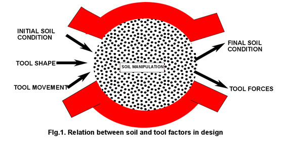
The implied relation between design factors is schematically represented in figure 2.1.
The generalized tillage relation can be mathematically represented by the two equations
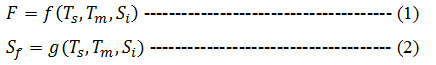
Where,
F = forces on the tool to cause movement,
Ts = tool shape,
Tm = manner of tool movement,
Si = initial soil condition,
f = functional relation between F, Ts, Tm, Si
Sf = final soil condition,
g = functional relation between Sf, Ts, Tm, Si.
Equation (1) is force tillage equation and equation (2) is soil condition tillage equation. The two equations represent the most general situation because, as written, the functional relations f and g are completely arbitrary. Furthermore, the two functions may or may not be different. The independence of the functional relations is of interest because of a possible higher order functional relation between F and Sf. If F and Sf are functionally related, equations 1 and 2 can be combined so that the relation between the design variables is represented by only one equation. Available knowledge does not conclusively indicate whether F and Sf should be related. The possibility thus exists that two separate equations inaccurately represent the generalized relations between the design factors.
Available mathematical knowledge helps to resolve the situation. Available mathematical theorems prove that F and Sf will be related only if the nature of f and g is such that their Jacobian is zero. Furthermore, the mathematics provides a means for determining the higher order relation if it exists. Thus, no mathematical restrictions are imposed on the possible functional relations if two equations are used. Two equations actually simplify the situation since each can be studied independently, although physically both equations operate simultaneously. From Equations 1 and 2, it is found that F and Sf are both dependent variables of the same independent variables. The general relation between the five design factors is, therefore, accurately represented by equations 1 and 2.
When designing a tillage tool for the purpose of establishing a new soil condition, our interest is no longer concentrated on the dynamic progress of the reaction of soil per se but rather on a soil tillage tool system and on the results of the reaction--the final soil condition. In design, an accurate description of how soil reacts is not essential. But the results of the reaction and what can be done to control the reaction are essential. Therefore, for design, our scope of interest must be concentrated on a quantitative description of the final soil condition and on how the manipulation can be controlled. The design factors and their relations indicated by equations 1 and 2 represent the desired quantitative descriptions for a scope of interest concerned with design.
The circle (fig. 2.1) hypothetically illustrates a change in our scope of interest. Inside the circle, the soil may be visualized as being manipulated. Forces cause the manipulation, so our scope of interest, centers on describing the reaction of soil to forces. Outside the circle, the results of the final soil condition and the control of the manipulation are of primary concern. The design scope of interest is thus represented by quantities operating outside the circle.
The procedural framework for designing a tillage tool is contained in equations 1 and 2. Knowledge of the functions represented in the equations would permit. a designer to use equation 2 to determine the resulting soil condition and equation 1 to determine the forces required to move the tillage tool. By simultaneously considering both equations, the possible tool shapes and movements could be optimized to effect the desired manipulation with minimum force. Since the functions are not yet known, the equations cannot be used directly for design. Even in their generalized functional form, however, they inherently establish guidelines for empirical design procedures.
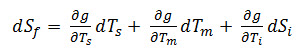
The total differential of equation of 1 is
![]() ------------------------ (3)
------------------------ (3)
and similarly the total differential of equation 2 is
 ----------------------- (4)
Equations 3 and 4 give the reasoning behind qualitative design procedures. For example, the shape of a tillage tool can be varied and the tool in each of its various shapes can be operated in a soil of uniform condition. If the movement of the tool is not changed (depth, width, speed, etc.), any change in the forces required to move the tool or any change in the results of the manipulation must come from the change in its shape. The conclusion is valid because equations 3 and 4 become, respectively,
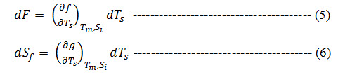
since dTm and dSi are both zero for the conditions of the observations. If one particular shape produces a soil manipulation that is judged to be superior, a description of that shape provides useful design information. Only the shape would need to be quantitatively described; the forces and the resulting soil change would not. The tool with the selected shape could be operated in various soil conditions to verify its action. If the required forces and the resultant soil manipulation were judged satisfactory, it could be concluded that the selected shape is an acceptable design for these soil conditions. Describing the soil conditions even in qualitative terms provides additional design information that can be associated with the description of the shape. Such procedures have led to the development of sod bottoms, general purpose bottoms, and slat bottoms for moldboard plows. The procedures were qualitative because numerical descriptions of all of the design factors were not necessarily used and no attempt was made to relate the design factors. Quantitative design procedures involve numerically relating the design factors to each other. If F and Ts are measured (numerically assessed) in circumstances that are accurately represented by equation 5, a unique relation between F and Ts must exist. The relation can be represented graphically by plotting the variables against each other. The plot results in a curve that represents the relation, and the equation for the curve is the solution of the differential equation in equation 5. The relation between Sf and Ts could be developed in a similar manner. Repeating the measurements in different soil conditions results in the development of a family of curves with each curve representing a constant soil condition. If the soil conditions are quantitatively described, relations between F and Si and Sf and Si for constant tool shape can be obtained. The equations that describe the relations provide the solutions to equations 3 and 4 when only the soil is varied. In a similar manner, tool movement can be varied when tool shape and initial soil conditions are constant to again provide equations to describe the indicated relations. Conceivably, all of these equations could be simultaneously considered or combined so that ultimately equations 1 and 2 could be developed. Quantitative design procedures, therefore, can lead to the development of the functions f and g in the tillage equations.
A certain group of tillage tools can be described geometrically by one equation or more. For example, all disks made from sections of spheres can be described by the equation for a sphere. The radius of the sphere and the limits that describe the section of the sphere from which the disk is made (diameter of the disk) become parameters of the geometrical description equations. Specifying a particular disk fixes the parameters of geometrical description equations just, as specifying a particular soil condition fixes the parameters of dynamic property equations. The system of equations forms a mechanics, and the solution of the system of equations can be obtained in terms of the parameters of both the soil (dynamic parameters) and the tool (geometrical parameters). The solution will be a tillage equation. From such a generalized solution, the effects of varying either the soil conditions for a specific tool or the tool for a fixed soil condition could be determined.
Another possible application of a general solution would be to consider only one specific tool. The path of motion could be expressed by equations, then mathematically varied, and the results determined. An elementary example of this approach would be in varying width and depth of operation. A generalized solution of the system of equations in terms of the parameters of soil (dynamic parameters) and path of motion parameters thus provides another tillage equation. In this instance the effects of varying either the soil path in fixed soil conditions or the soil conditions for a fixed soil path could be determined. The general procedure described here provides a means for determining tillage equations to form a soil tillage tool mechanics.
Since many design equations must, exist, a technique for representing a design factor may aid in developing tillage equations. Recall that behavior equations were said to contain parameters, and these parameters assessed the contribution of the material to the behavior. In a similar manner, parameters of tillage equations can be used to represent one of the independent design factors.
To illustrate the technique, consider a situation where equation 5 is applicable. Assume that a relation between F and Ts is experimentally obtained and is graphically represented. The resulting curve represents the relation between F and Ts at a constant soil condition and a constant manner of movement. If the measurements are repeated in a different soil condition the resulting curve probably will be different. By repeating the measurements in several soil conditions, a series of curves can be developed. The difference between curves reflects the difference between initial soil conditions. Assume that the curves are all similar and that an equation can be developed that represents the curves. The equation that describes all of the curves can be said to be a general equation. To be a general equation, rather than a specific equation, it must contain parameters. These parameters will numerically assess the initial soil condition. For example, if the relation between F and Ts is linear, the intercept and slope are parameters of the equation and they would numerically assess Si in the tillage equation. Each different soil condition will have a different slope and intercept. If the manner of tool movement were changed, rather than initial soil conditions, a different family of curves would result. Developing a general equation to represent the curves again will define parameters. In this case they will assess the manner of movement rather than the initial soil condition. In short, the technique provides a means to numerically define and assess one of the independent variables in the tillage equation.
The technique has one serious limitation. Just as behavior equations define behavior parameters, so tillage equations define design parameters. Consequently, the design parameters are defined by the soil-tillage tool system. In order to assess the parameters, a particular tool must be physically operated in a manner that simulates the system being represented. Once the parameters have been assessed, all similar tools can be described by the equations. The cutting parameters were defined by the mechanics of cutting rather than by a behavior equation. The limitation could possibly be minimized if the design parameters could be related to some other defined factor in the system. For example, if the design parameters assess the soil, they must be determined by the material and state properties of the soil just as dynamic behavior parameters must be determined by these same soil properties. Establishing the relation would overcome the limitation of the technique.
The need for design information and the complexity of the relations involved between the design factors clearly indicate that both the empirical approach and the derived approach should be simultaneously followed. Each approach requires certain facilities and interests. The empirical approach requires facilities for keeping soil condition constant and for producing various shapes of tools and equipment for controlling the manner of movement. As equations 3 and 4 indicate, control must be sufficient so that any change in F or Sf can be attributed to the correct design factor. In the derived approach, soil behavior can often be studied with small samples of soil and rather simple apparatus. A mechanics based on behavior equations can be developed with only a pencil and paper. Facilities and personal interest, therefore, should partly determine the approach to follow. In the empirical approach, however, emphasis must be placed on establishing quantitative relations. Only when design information must be immediately available should qualitative empirical procedures be followed. Qualitative procedures can never lead to the information needed for design where control of soil manipulation is possible. Finally, one should recognize that a complete understanding of the general behavior of soil reacting to a tillage tool can be obtained only from knowledge based on scientific principles. Such principles can never be deduced from an empirical description of general behavior. Therefore, the derived approach will ultimately have to be fully developed before a complete understanding of the soil-tillage tool system can be attained.
Last modified: Thursday, 13 February 2014, 11:28 AM